Combined implantation source applicator

A source applicator and implant technology, which is applied in the field of radiotherapy, can solve the problems of few types of individual implant applicators, time-consuming procedures, and high requirements for doctors' proficiency, so as to shorten waiting time, improve fixation, and relieve pain Effect

Pending Publication Date: 2019-08-23
SICHUAN CANCER HOSPITAL
View PDF0 Cites 6 Cited by
  • Summary
  • Abstract
  • Description
  • Claims
  • Application Information

AI Technical Summary

Problems solved by technology

However, the existing intracavitary + implantation technology has problems such as long process time, few types of individualized implantation applicators, and high requirements for doctors' proficiency.

Method used


Image

  • Combined implantation source applicator
  • Combined implantation source applicator
  • Combined implantation source applicator

Examples


Embodiment 1

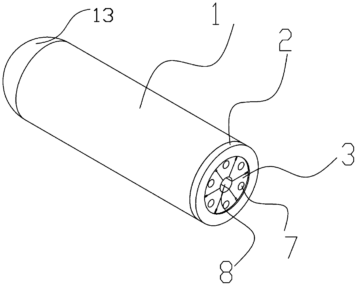
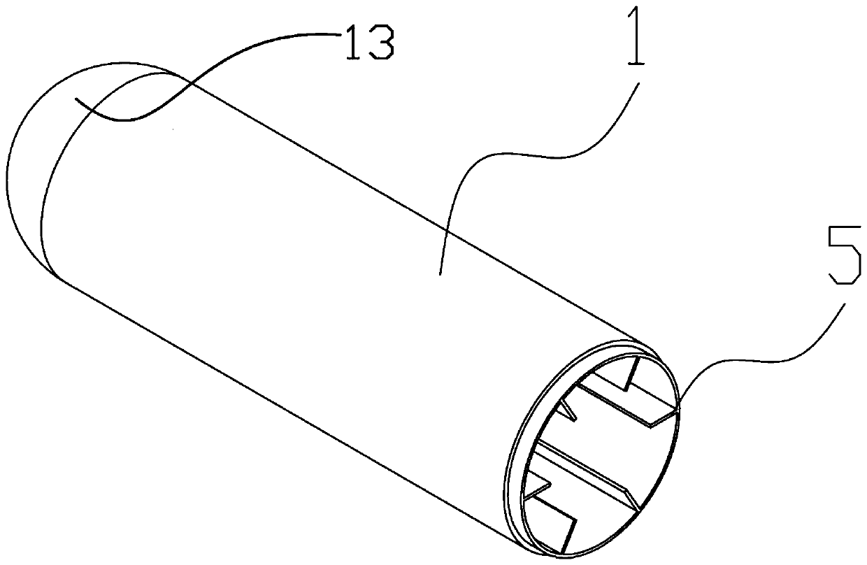
[0036] Such as figure 1 , figure 2 , image 3 , Figure 4 , Figure 8 and Figure 9 As shown, a combined planting applicator includes a sleeve 1, a fixed cap 2 and several combination blocks 3, one end of the sleeve 1 is provided with a sealing member 13 in the shape of a spherical segment, and the fixed cap 2 can be The other end connected to the sleeve 1 is disassembled, and the fixed cap 2 is provided with a through hole 4;

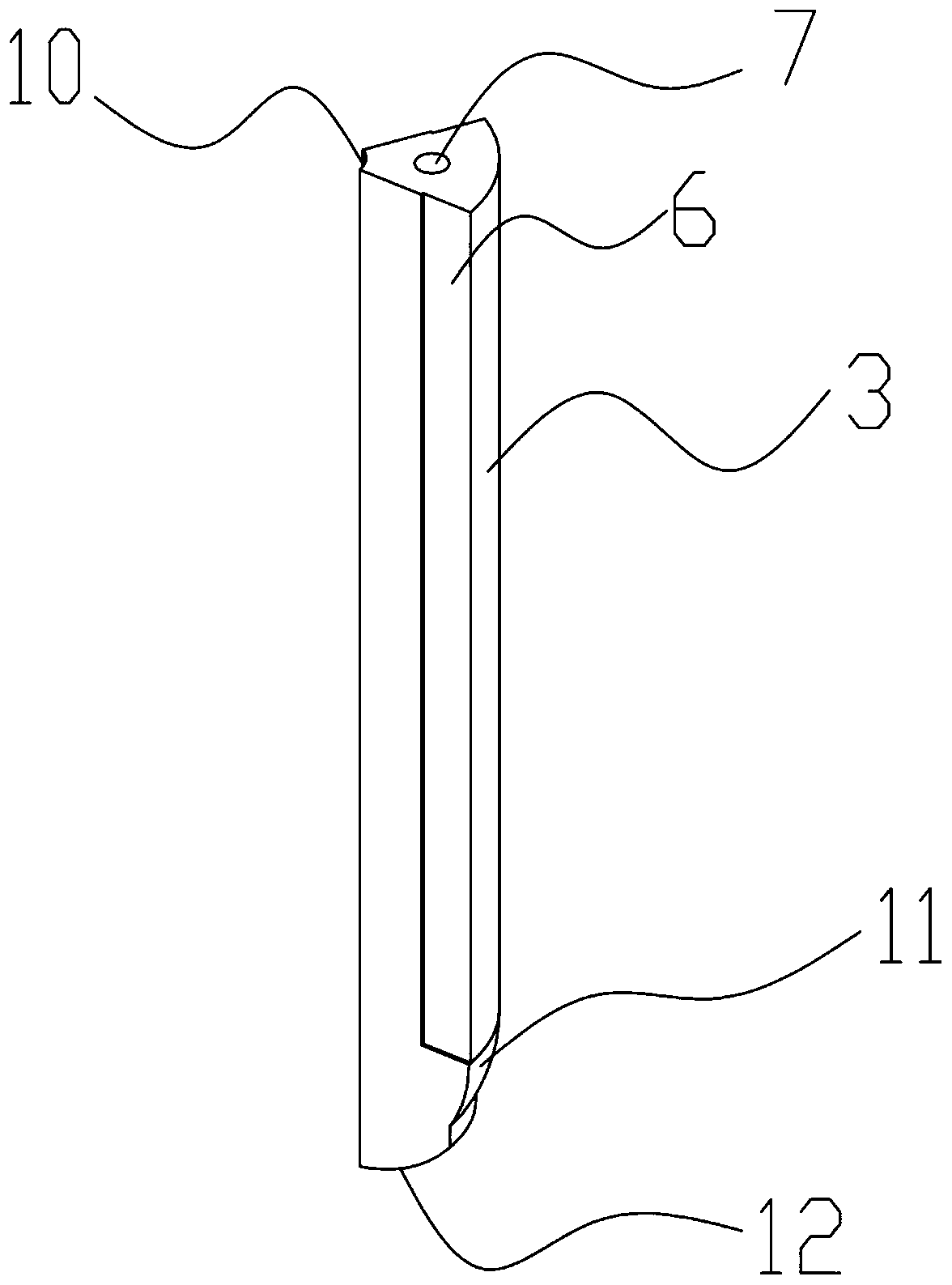
[0037] On the inner side wall of the sleeve 1 there are evenly distributed along its circumference a number of limiting plates 5 for limiting the combined block 3, and the combined block 3 is provided with a card slot 6 corresponding to the limiting plate 5, The combination block 3 is arranged in the sleeve 1, and is combined with the sleeve 1 to form a cylinder after being limited by the limiting plate 5; one end of the combination block 3 is connected to the inner side of the sealing member 13 The wall fits, and the other end fits with the fix...

Embodiment 2

[0041] Such as Figure 5-7 As shown, this embodiment is based on Embodiment 1, the seal 13 of the sleeve 1 is provided with an opening 9 for the exposure of the applicator, the insertion hole 7 and the placement hole 8 are separated from the exposed through the opening.

[0042] The purpose of setting the opening 9 on the sealing member 13 of the sleeve 1 is to make the sleeve 1 into two types, the penetrating end type and the non-penetrating end type, and the doctor can choose the penetrating end type or the non-penetrating end type according to the actual needs of the patient.

Embodiment 3

[0044] Such as Figure 1-9 As shown, this embodiment is based on Embodiment 1. The arc-shaped end of the combination block 3 includes a bayonet portion 11 and a fitting portion 12. The curvature of the bayonet portion 11 is consistent with the sleeve 1 The curvature of the bottom inner side wall of the sleeve 1 matches the curvature of the bottom inner side wall, and the curvature of the fitting part 12 matches the curvature of the bottom outer side wall of the sleeve 1; the combination block 3 is installed in the sleeve 1 provided with an opening, and the After the bayonet part 11 is bonded to the inner wall of the sealing member 13 of the sleeve 1 , a spherical segment is formed with the bonding part.

[0045] The arc-shaped end of the combination block 3 includes a bayonet part 11 and a bonding part 12. After the bayonet part 11 is bonded to the inner side wall of the bottom of the sleeve 1, it forms a spherical segment with the bonding part 12. When the sleeve 1 is shaped...


PUM


Abstract

The invention discloses a combined implantation source applicator. The combined implantation source applicator comprises a sleeve, a fixed cap and multiple combination blocks; a segment-shaped sealingpart is arranged at one end of the sleeve, the fixed cap is detachably connected to the other end of the sleeve, and a through hole is formed in the fixed cap; multiple limiting plates used for limiting the combination blocks are uniformly distributed on the inner side wall of the sleeve in the circumferential direction, clamping grooves corresponding to the limiting plates are formed in the combination blocks, and the combination blocks are arranged in the sleeve, limited through the limiting plates and then spliced with other combination blocks to form a cylinder; the end, in fit connectionwith the sealing part, of each combination block is shaped like an arc; a notch is formed in the surface of each combination block in the axis direction, an insertion hole used for installing an implantation needle is formed in the center of each combination block in the axis direction, and a notch formed after all the combination blocks are spliced is a placing hole used for installing the intracavity source applicator. The combined implantation source applicator has the advantages that free combination can be conducted according to the conditions of patients, and individual treatment of thepatients is met.

Description

technical field [0001] The invention relates to the technical field of radiotherapy, in particular to a combined implant applicator. Background technique [0002] Cervical cancer is one of the more common malignant tumors among women in my country. According to the latest national cancer statistics released by the National Cancer Center in 2018, cervical cancer ranks sixth in the incidence of female tumors, with an incidence rate of 6.04%. Radiation therapy is one of the three major means of cervical cancer treatment, external radiation therapy combined with afterloading is the standard mode of radiation therapy for cervical cancer. The screening of cervical lesions in our country is still not perfect, and some patients have developed locally advanced disease when they are diagnosed. External radiation combined with simple intracavitary retroloading therapy has a good effect on early cervical cancer, but has limitations on locally advanced cervical cancer. Post-implantatio...

Claims


Application Information

Patent Timeline
Patent Type & Authority Applications(China)
IPC IPC(8): A61N5/10
CPCA61N5/1002A61N5/1007A61N2005/101
Inventor 王先良王培黎杰康盛伟谭燕
Owner SICHUAN CANCER HOSPITAL
Why Eureka
Try Eureka