A biomimetic snake-like robot

A bionic snake and robot technology, applied in the field of robotics, can solve the problems of not being able to be better applied, not being able to crawl on soft ground, and not having the ability to overcome obstacles.

Active Publication Date: 2020-09-15
泉州市中知信息科技有限公司
View PDF1 Cites 3 Cited by
  • Summary
  • Abstract
  • Description
  • Claims
  • Application Information

AI Technical Summary

Problems solved by technology

The joints of the snake robot include the front joint arm, the rear joint arm, the steering gear, the steering gear mounting frame and the steering wheel, and the steering gear is installed on the steering gear mounting frame; Ⅱ, side wings Ⅱ are installed on the rudder disc, and there is a connection hole Ⅰ on the bottom of the arm; the rear joint arm includes an L-shaped connection installation part and a joint connection part, the installation part is installed on the steering gear mounting frame, the joint connection part and the arm The bottom is parallel, and there is a connection hole II on the joint connection part; the disadvantage of this utility model is that it cannot perform two free movements in the plane, does not have a certain ability to overcome obstacles, and cannot be better suitable for gaps in earthquake rescue. Walk through, and not suitable for crawling on soft ground

Method used


Image

  • A biomimetic snake-like robot
  • A biomimetic snake-like robot
  • A biomimetic snake-like robot

Examples


specific Embodiment approach 1

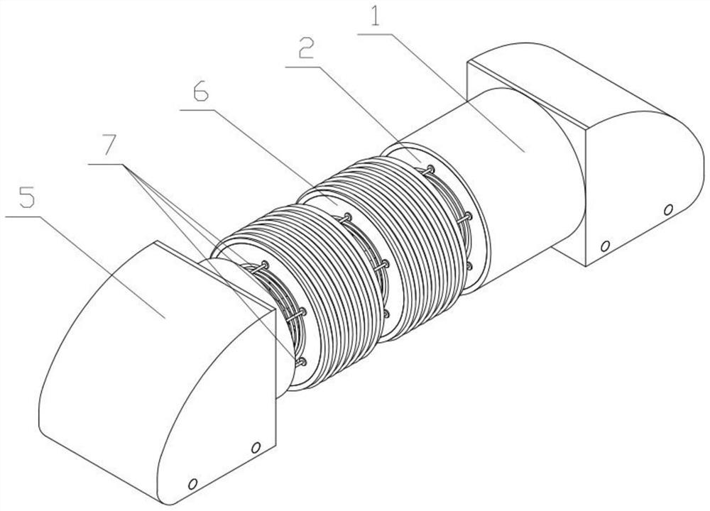
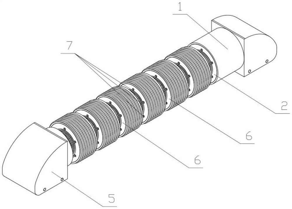
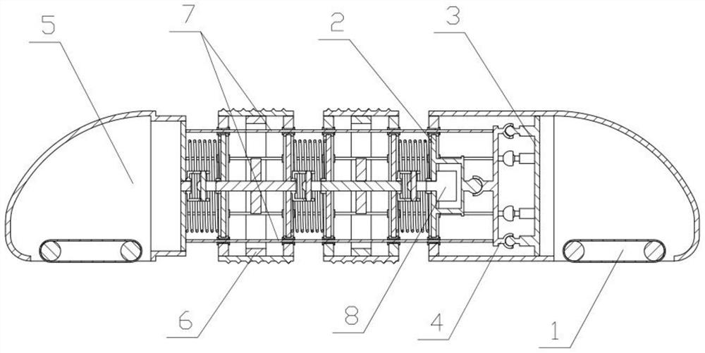
[0042] Combine below Figure 1-16 In this embodiment, a biomimetic snake-shaped robot includes a head support 1, a support frame 2, a pushing mechanism 3, a deflection mechanism 4, a tail support 5, a moving body 6, a stretched wire rope 7 and a power mechanism 8. The head support 1 and the tail support 5 support the rotation of the power mechanism 8. The power mechanism 8 drives multiple moving bodies 6 to rotate while rotating, and the multiple moving bodies 6 are pushed by walking spirals 6-7 when rotating. The device moves. Since the multiple walking spirals 6-7 are circular, each walking spiral 6-7 on the multiple walking spirals 6-7 can push the device to move as long as there is a contact surface around it. It is suitable for traveling through soft ground, pipelines or building gaps in earthquake rescue. The relative length of the multiple tensile steel ropes 7 through the multiple moving bodies 6 is changed by the deflection mechanism 4 to squeeze the compression spring...

specific Embodiment approach 2

[0049] Combine below Figure 1-16 This embodiment will be described. This embodiment will further explain the first embodiment. The head support 1 includes a head support body 1-1, a mounting cylinder 1-2, and crawler wheels I1-3, and a head support body 1-1 The upper part is fixedly connected with a mounting cylinder 1-2, the deflection bottom plate 4-1 and the support ring I2-1 are both fixedly connected in the mounting cylinder 1-2, and the crawler wheel I1-3 is rotatably connected to the lower part of the head bracket body 1-1. Side; the head support body 1-1 plays a role in supporting and rotating the device to a certain extent. The support ring Ⅱ6-1 is rotated and limited by the contact between the head support body 1-1 and the ground. The extension wire rope 7 limits the rotation direction of the support ring Ⅱ6-1 to ensure that the support ring Ⅱ6-1 will not rotate along with the walking spiral 6-7. The crawler travel wheel I1-3 reduces friction, and the crawler travel ...

specific Embodiment approach 3

[0051] Combine below Figure 1-16 This embodiment will be described. This embodiment will further explain the second embodiment. The head support body 1-1 is provided with a visual sensor and a thermal sensor, and both the visual sensor and the thermal sensor are connected to the computer through signals; During rescue or walking in the pipeline, the visual sensor and thermal sensor can collect information and transmit it to the computer.


PUM


Abstract

The invention relates to robots, in particular to a biology bionic snake-like robot. A head support, a supporting frame, a pushing mechanism, a deflection mechanism, a tail support, motion bodies, stretching steel wire ropes and a power mechanism are included. The power mechanism drives the multiple motion bodies to rotate during rotation. The multiple motion bodies move through a walking spiral pushing device during rotation. Since a plurality of walking spirals are each in a circular ring shape, each of the multiple walking spirals can push the device to move as long as the contact face exists on the periphery, and the biology bionic snake-like robot can be better applicable to the soft ground and pipelines or pass through building gaps during earthquake rescue. Through the deflection mechanism, the relative length of the parts, penetrating through the multiple motion bodies, of the multiple stretching steel wire ropes is changed, compression springs are extruded, bending happens between the multiple motion bodies, the device can conduct the two-freedom motion in the plane, and a certain obstacle crossing capability is achieved.

Description

Technical field [0001] The present invention relates to a robot, more specifically, a biomimetic snake-shaped robot. Background technique [0002] For example, the publication number CN204935672U names a snake-shaped robot joint and a snake-shaped robot. Snake-shaped robot joints include front articulated arm, rear articulated arm, steering gear, steering gear mounting frame and steering wheel. The steering gear is mounted on the steering gear mounting frame; the front articulated arm includes a U-shaped distributed arm bottom, side wing I and side wing Ⅱ. The side wing Ⅱ is installed on the rudder plate, and the arm bottom is provided with a connecting hole I; the rear articulated arm includes an L-shaped connecting mounting part and a joint connecting part, the mounting part is installed on the steering gear mounting frame, the joint connecting part and the arm The bottom is parallel, and the joint connection part is provided with a connection hole Ⅱ; the disadvantage of this ...

Claims


Application Information

Patent Timeline
Patent Type & Authority Patents(China)
IPC IPC(8): B25J9/06B25J9/12
CPCB25J9/065B25J9/102B25J9/109B25J9/12
Inventor 李忠吉
Owner 泉州市中知信息科技有限公司
Why Eureka
Try Eureka