Supercharge Your Innovation With Domain-Expert AI Agents!

A differential filling device for metal powder bagging

A technology of powder bagging and differential filling, which is applied in the field of differential filling devices for metal powder packaging, which can solve the problems of difficult differential filling and large filling volume errors, and achieve high filling efficiency

Inactive Publication Date: 2020-12-08
张素烨
View PDF4 Cites 0 Cited by
  • Summary
  • Abstract
  • Description
  • Claims
  • Application Information

AI Technical Summary

Problems solved by technology

[0003] In view of this, the present invention provides a differential filling device for metal powder bagging to solve the problem in the prior art that the filling volume error is large and it is not easy to fill the differential; the present invention can fill the metal powder Metal powder is added to the packing box after powder, and different differential metal powder can be added according to the set quality

Method used


Image

  • A differential filling device for metal powder bagging
  • A differential filling device for metal powder bagging
  • A differential filling device for metal powder bagging

Examples


Embodiment 1

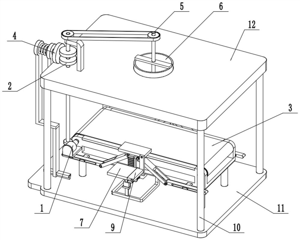
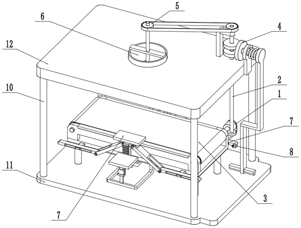
[0033] Such as Figure 1-13As shown, a differential filling device for metal powder bagging includes a driving mechanism 1, a linkage wheel 2, an output belt 3, a material control linkage 4, a feeder 5, a feeding cylinder 6, a differential balance mechanism 7, Interrupt the top plate 8, the upper seat plate 12, the support column 10 and the lower seat plate 11, the drive mechanism 1 is fixed on the output belt 3, and the drive mechanism 1 is connected to the output belt 3 and the linkage wheel 2; the output belt 3 is fixed on the lower seat on the plate 11; the linkage wheel 2 is rotatably connected to the upper seat plate 12, the linkage wheel 2 is connected to the material control linkage 4 by transmission, and the upper and lower ends of the material control linkage 4 are respectively fixedly connected to the upper seat plate 12 and the lower seat plate 11; The material control linkage 4 is connected to the feeder 5 through transmission, and one end of the feeder 5 is fixed...

Embodiment 2

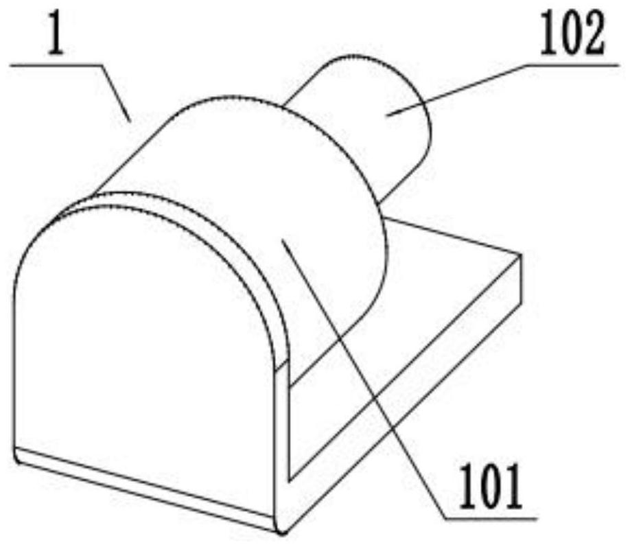
[0035] Such as Figure 1-13 As shown, the drive mechanism 1 includes a servo motor 101 and a worm 102 fixed on the output shaft of the servo motor 101; the servo motor 101 is fixed on the output belt 3 through a motor base; the worm 102 is connected to the output belt 3 and Linkage wheel 2. The servo motor 101 can drive the worm screw 102 to rotate around its own axis after being powered on and turned on, and the output belt 3 and the linkage wheel 2 can be driven to start working when the worm screw 102 rotates.

Embodiment 3

[0037] Such as Figure 1-13 As shown, the linkage wheel 2 includes a worm wheel 201, a first rotating shaft 202 and a friction transmission wheel 203; the middle part of the first rotating shaft 202 is rotatably connected to the upper seat plate 12; the upper and lower ends of the first rotating shaft 202 are respectively fixed The friction transmission wheel 203 is connected to the worm wheel 201; the worm 102 is meshed with the worm wheel 201; the friction transmission wheel 203 is connected to the material control linkage 4 through friction transmission. The worm wheel 201 rotates under the drive of the worm screw 102. The rotation of the worm wheel 201 drives the first rotating shaft 202 to rotate around its own axis.


PUM


Abstract

The present invention relates to the field of metal powder filling, and in particular, to a difference quantity filling apparatus for metal powder bagging; the apparatus includes a driving mechanism,an engaged wheel, an output belt, a material control linkage device, a material unloading apparatus, a material filling cylinder, a difference quantity balancing mechanism, an interrupt top plate, anupper base plate, support posts, and a lower base plate, wherein the driving mechanism is fastened to the output belt, and is in transmission connection to the output belt and the engaged wheel; the output belt is fastened to the lower base plate; the engaged wheel is in rotatable connection to the upper base plate, and is in transmission connection to the material control linkage device; upper and lower ends of the material control linkage device are fixedly connected to the upper base plate and the lower base plate, respectively; and the material control linkage device is in transmission connection to the material unloading apparatus, one end of the material unloading apparatus is fastened to the upper base plate, and the other end of the material unloading apparatus is in rotatable connection to the material filling cylinder. In the present invention, metal powder may be added into a packaging box filled with metal powder, and metal powder with different difference quantities may beadded according to set quality.

Description

technical field [0001] The invention relates to the field of metal powder filling, in particular to a differential filling device for metal powder bagging. Background technique [0002] Metal powder filling is an indispensable process in the process of metal powder processing, production and packaging in the prior art. In the prior art, when the metal powder is loaded into the box, the error of the filling amount of the metal powder is relatively large, so It is very inconvenient to weigh and measure the loaded mass before adding metal powder. Contents of the invention [0003] In view of this, the present invention provides a differential filling device for metal powder bagging to solve the problem in the prior art that the filling volume error is large and it is not easy to fill the differential; the present invention can fill the metal powder Metal powder is added to the packed box after powder, and different amounts of metal powder can be added according to the set qu...

Claims


Application Information

Patent Timeline
Patent Type & Authority Patents(China)
IPC IPC(8): B65B1/30B65B61/28
CPCB65B1/30B65B61/28
Inventor 张素烨
Owner 张素烨
Features
  • R&D
  • Intellectual Property
  • Life Sciences
  • Materials
  • Tech Scout
  • Unparalleled Data Quality
  • Higher Quality Content
  • 60% Fewer Hallucinations
Learn More