
Conical roller bearing for differential mechanism

A technology of tapered roller bearings, differentials, applied in the direction of ball bearings, bearing elements, shafts and bearings

Active Publication Date: 2019-08-23
C&U CO LTD +2
View PDF5 Cites 0 Cited by
  • Summary
  • Abstract
  • Description
  • Claims
  • Application Information

AI Technical Summary

Problems solved by technology

[0003] However, in the existing technology, when it is in use, due to the excessive lubricating oil entering the bearing, the cage and the rollers will be stirred with the lubricating oil during the rotation process, resulting in additional energy consumption

Method used


Image

  • Conical roller bearing for differential mechanism
  • Conical roller bearing for differential mechanism
  • Conical roller bearing for differential mechanism

Examples


Embodiment Construction

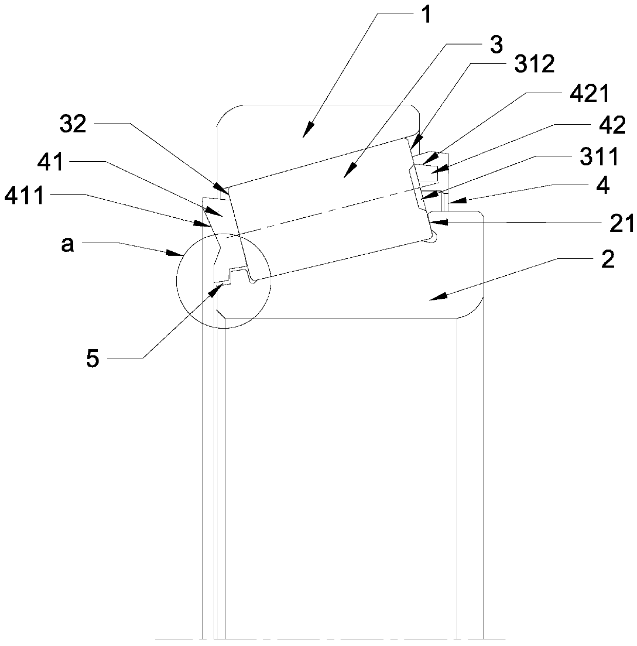
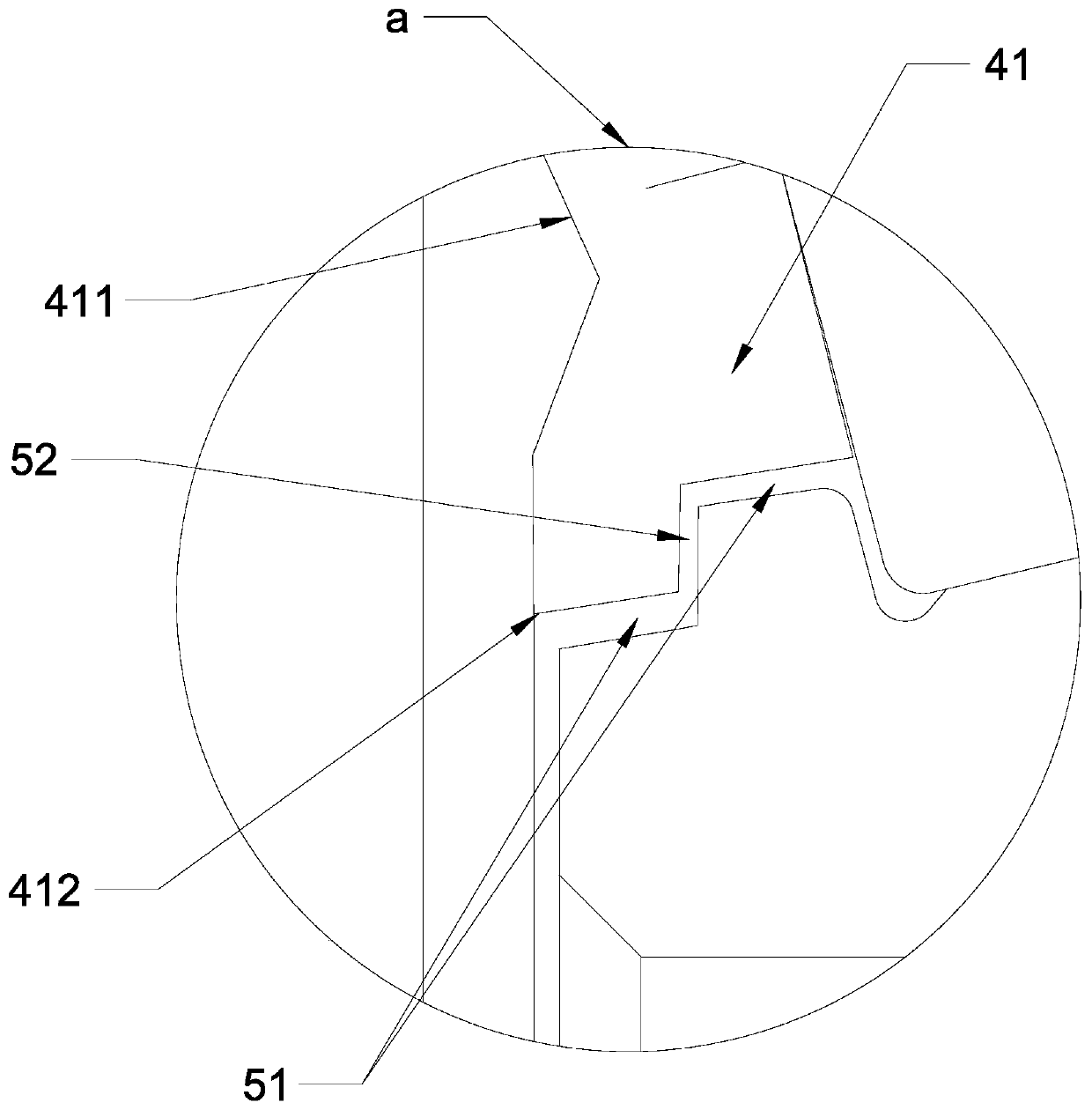
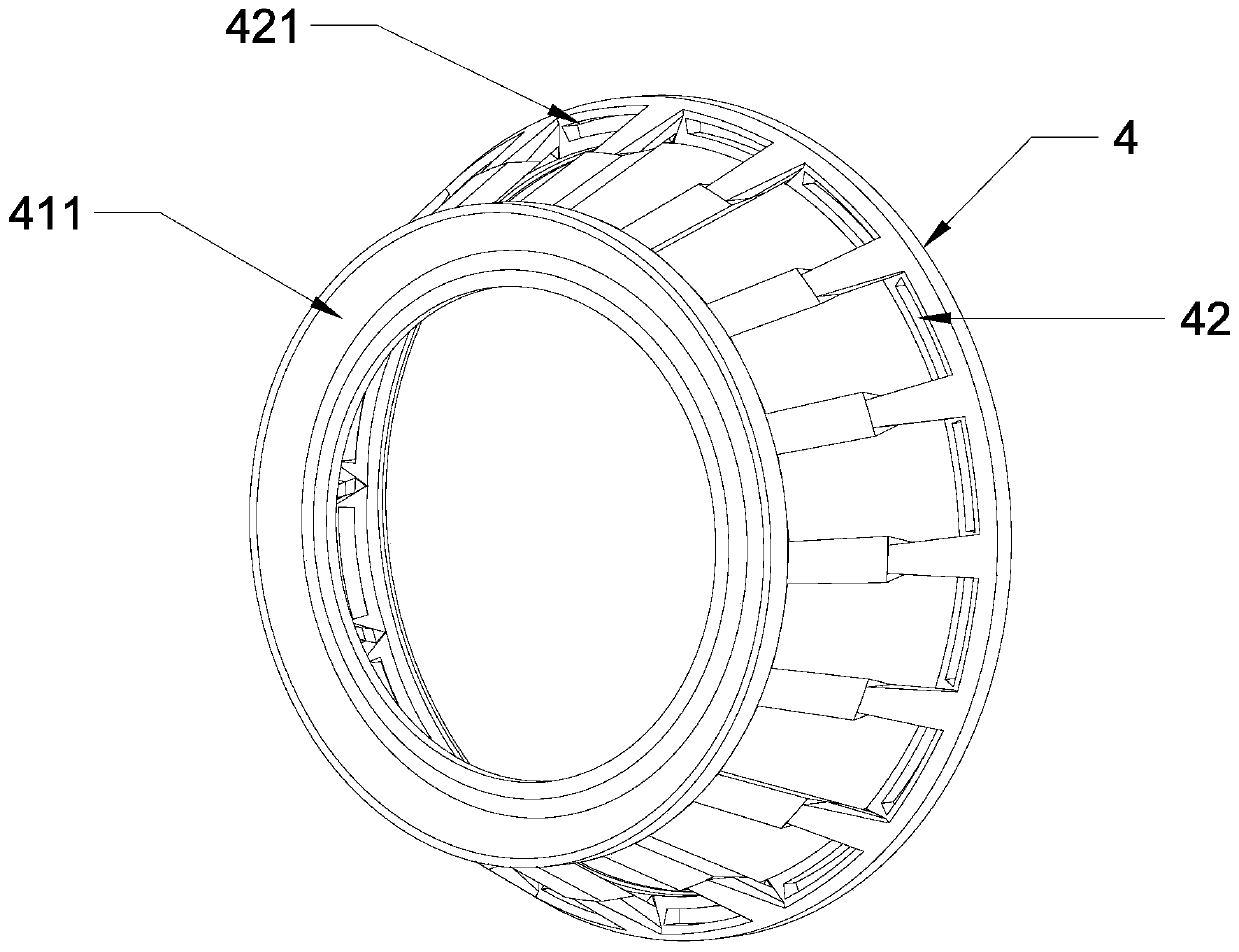
[0027] Embodiment 1 of the tapered roller bearing of the present invention is as Figure 1-4 Shown: It includes an outer ring 1, an inner ring 2, a roller 3, and a cage 4. The roller 3 includes a big end 31 and a small end 32. The cage 4 includes a small roller The annular recess 41 at the end 32, the annular recess 41 is arranged along the axis of the roller 3 toward the outside of the bearing, the annular recess 41 includes an oil sling surface 411 arranged near the outer ring of the bearing, and the oil sling surface 411 It is arranged obliquely toward the outside of the bearing, and the inner edge of the annular recess 41 and the inner ring of the bearing form a restricted flow channel 5. The annular recess 41 and the holder 4 are processed from a piece of profile material. In this embodiment, the annular recess 41 and the holder 4 are stamped and formed from metal materials. The restriction passage 5 is stepped, and the restriction passage 5 includes two drainage sections...


PUM


Abstract

The invention provides a conical roller bearing for a differential mechanism. The conical roller bearing comprises an outer ring, an inner ring, a roller and a retainer, wherein the roller comprises abig end and a small end; the retainer comprises an annular concave part located at the small end of the roller; the annular concave part is arranged toward the outer side of the bearing along the axis of the roller; the annular concave part comprises an oil throwing surface arranged at a part close to the outer ring of the bearing; the oil throwing surface is obliquely arranged toward the outer side of the bearing; and a flow limiting channel is formed through an inner edge of the annular concave part and the inner ring of the bearing. The invention provides the conical roller bearing for thedifferential mechanism, which can prevent excessive lubricating oil from entering the bearing and reduce the extra loss.

Description

Technical field [0001] The invention relates to a bearing, in particular to a tapered roller bearing for a differential. Background technique [0002] Tapered roller bearing is a radial thrust rolling bearing with conical rollers. This type of bearing is mainly used in high rigidity and continuous operation. It can provide stable performance in limited space and compact layout, so it is often Used in automobile differentials, it usually includes an outer ring, an inner ring, a roller, and a cage for isolating the roller. The roller is conical and includes a big end and a small end , A raceway for the rollers is formed between the outer ring and the inner ring, and oil grooves are provided on both ends of the corresponding rollers. Because of the tapered roller bearing, there is an axial direction toward the small end of the roller. Force component, usually two small ends facing each other are used as a set of bearings to offset the axial component force, and because the differen...

Claims


Application Information

Patent Timeline
IPC IPC(8): F16C19/16F16C33/36F16C33/42F16C33/58F16C33/66
CPCF16C19/16F16C33/366F16C33/42F16C33/583F16C33/6603
Inventor 白雪峰
Owner C&U CO LTD
Learn More