Wear-free ball valve

A wear-free, ball valve technology, applied in valve details, valve device, valve operation/release device, etc., can solve the problems of shortening the service life of the ball valve, wear and tear, and reducing the reliability of the ball valve, so as to improve the service life and improve the sealing. The effect of reliability

Active Publication Date: 2019-08-23
ZHEJIANG XINDA VALVE
View PDF7 Cites 7 Cited by
  • Summary
  • Abstract
  • Description
  • Claims
  • Application Information

AI Technical Summary

Problems solved by technology

However, in order to ensure that no internal leakage occurs in the existing ball valves, the ball, that is, the closing part, must be tightly pressed on the valve seat during installation. The torque is large when opening

Method used


Image

  • Wear-free ball valve
  • Wear-free ball valve
  • Wear-free ball valve

Examples


Embodiment Construction

[0015] The present invention will be further described in detail below in conjunction with the accompanying drawings and embodiments.

[0016] Such as Figure 1-7 Shown is a preferred embodiment of the present invention.

[0017] A ball valve comprising

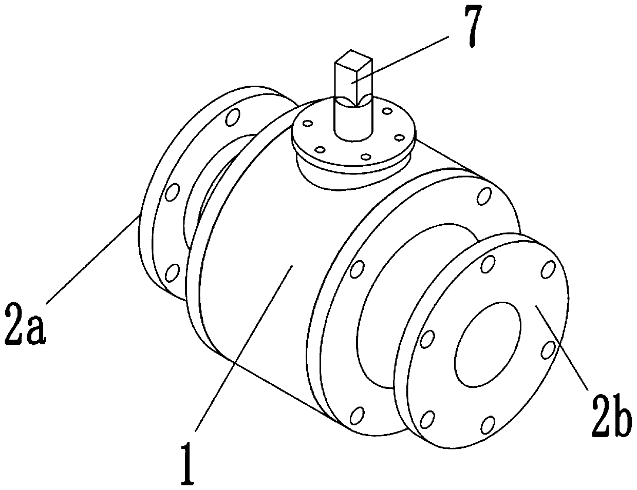
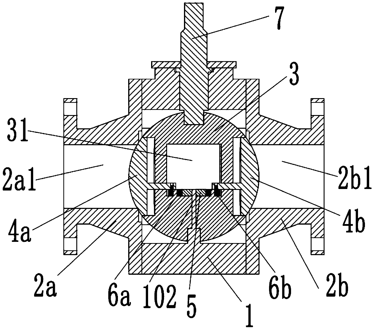
[0018] The valve body 1 is provided with a cavity 101 penetrating left and right inside the valve body 1 , and a rotating shaft 102 is fixedly installed below the cavity 101 .

[0019] The left valve cover 2a is fixedly installed on the left end of the valve body 1 , and the left valve cover 2a is provided with a first flow channel 2a1 communicating with the cavity 101 .

[0020] The right valve cover 2b, the right valve cover 2b is fixedly installed on the right end of the valve body 1, and the second flow channel 2b1 communicating with the cavity 101 is provided in the right valve cover 2b.

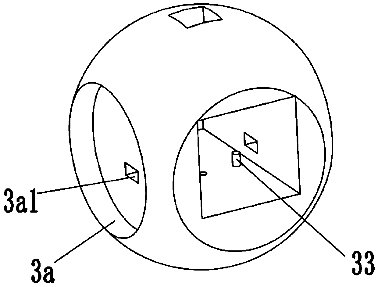
[0021] The valve ball 3, the valve ball 3 is rotatably arranged in the cavity 101, the lower end of the valve ball 3 is rotatably ...


PUM


Abstract

The invention relates to a ball valve comprising a valve body, a left valve deck, a right valve deck, a valve ball, a left valve clack, a right valve clack, a large gear, a left small gear, a right small gear and a drive shaft. The valve body is internally provided with a cavity body and a rotating shaft. The left valve deck and the right valve deck are fixedly installed at the two ends of the valve body correspondingly. The valve ball is arranged in the cavity body in a rotatable manner. The valve ball is internally provided with a left valve cavity, a right valve cavity and a rectangular circulation window. The left valve clack and the right valve clack are arranged in the left valve cavity and the right valve cavity correspondingly. The large gear is fixedly installed on the rotating shaft and located in the circulation window. The left small gear and the right small gear are connected with the left valve clack and the right valve clack correspondingly and are both engaged with thelarge gear. The drive shaft is used for driving the valve ball to rotate. According to the ball valve, in the opening process, no friction or wear is caused to the left valve clack and the right valveclack, and the service life can be prolonged.

Description

technical field [0001] The invention belongs to the technical field of pipeline valves, in particular to a wear-free ball valve. Background technique [0002] Pipelines are usually used to transport media in industrial or civil infrastructure, where the pipeline is regulated due to changes in pressure or temperature. In order to adjust the flow, an adjustment mechanism, especially a ball valve, is used in the pipeline to ensure the best work. conditions and the safety of the environment. Ball valves usually use a sphere with a circular passage as the opening and closing element, and the sphere realizes the opening and closing action with the rotation of the valve body. The opening and closing part of the ball valve is a ball with a through hole, which rotates around the axis perpendicular to the channel, so as to achieve the purpose of opening and closing the channel. A traditional ball valve is usually a sphere with a through hole installed on the valve seat, and the open...

Claims


Application Information

Patent Timeline
IPC IPC(8): F16K5/06F16K5/20F16K31/53
CPCF16K5/0605F16K5/204F16K31/535
Inventor 不公告发明人
Owner ZHEJIANG XINDA VALVE
Why Eureka
Try Eureka