Leakage-proof device and installation method of construction pipeline interface

A technology of pipe joints and leak-proof devices, which is applied in the direction of pipe joints, pipe systems, pipes/pipe joints/fittings, etc., can solve problems such as troubles, and achieve the effects of convenient processing, avoiding losses, and saving installation time and effort

Active Publication Date: 2019-08-23
夏献云
View PDF6 Cites 12 Cited by
  • Summary
  • Abstract
  • Description
  • Claims
  • Application Information

AI Technical Summary

Problems solved by technology

[0003] The purpose of the present invention is to solve the shortcomings in the prior art that the leak-proof device needs to be fixed by using multiple bolts or welding, which is troublesome and cannot meet people's use needs, and proposes a construction pipeline Interface leak-proof device and installation method

Method used


Image

  • Leakage-proof device and installation method of construction pipeline interface
  • Leakage-proof device and installation method of construction pipeline interface
  • Leakage-proof device and installation method of construction pipeline interface

Examples


Embodiment 1

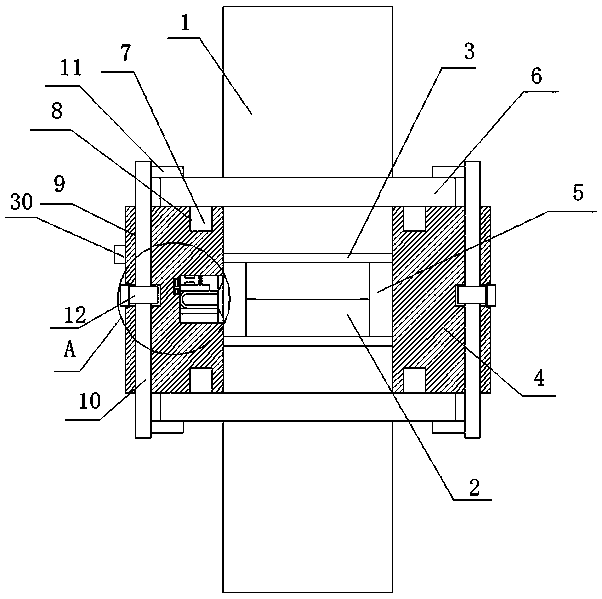
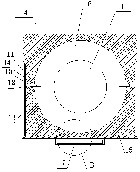
[0030] refer to Figure 1-6 , a leak-proof device for building pipe joints, comprising two pipes 1, one end of a joint 2 is fixedly installed on the sides of the two pipes 1 close to each other, the other ends of the two joints 2 are in contact, and the outer sides of the two pipes 1 The same connection seat 4 is installed, and a connection hole 5 is opened on the connection seat 4, and the two joints 2 are located in the connection hole 5, and the outer sides of the two joints 2 are fixedly provided with sealing rings 3, and the two sealing rings 3 are Sealed with the connection hole 5, the outer sides of the two pipes 1 are fixedly provided with an annular plate 6, and the sides of the two annular plates 6 that are close to each other are respectively in contact with the top and bottom of the connecting seat 4, and the connecting seat 4 is provided with a fixed Mechanism, the fixing mechanism cooperates with two annular plates 6.

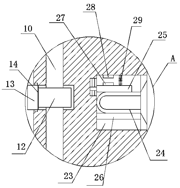
[0031] In the present invention, the fixin...

Embodiment 2

[0044] refer to Figure 1-6 , a leak-proof device for building pipe joints, comprising two pipes 1, the sides of the two pipes 1 close to each other are fixed with one end of the joint 2 by welding, the other ends of the two joints 2 are in contact, and the two pipes 1 The same connecting seat 4 is installed on the outer side of the connecting seat 4, and a connecting hole 5 is opened on the connecting seat 4, and the two joints 2 are located in the connecting hole 5, and the outer sides of the two joints 2 are fixedly sleeved with a sealing ring 3, and the two sealing rings 3 are sealed with the connection hole 5, and the outer sides of the two pipes 1 are fixedly provided with an annular plate 6, and the sides of the two annular plates 6 that are close to each other are respectively in contact with the top and bottom of the connecting seat 4, and the connecting seat 4 is provided with There is a fixing mechanism, which cooperates with the two annular plates 6 .

[0045] In ...


PUM


Abstract

The invention belongs to the leakage-proof field of a pipeline interface, in particular to a leakage-proof device and an installation method of a construction pipeline interface; aiming at the problemthat the existing leakage-proof device needs to be fixed by using a plurality of bolts or a welding method when being installed, which is troublesome and cannot meet the using needs of users, and nowthe following scheme is proposed; the leakage-proof device comprises two pipelines; one sides, close to each other, of the two pipelines are fixedly installed at one ends of joints; the other ends ofthe two joints contact with each other; the outer sides of the two pipelines are provided with the same connecting base; a connecting hole is formed in the connecting base; the two joints are locatedin the connecting hole; the outer sides of the two joints are fixedly sleeved with sealing rings, the two sealing rings are sealed and matched with the connecting hole; and the outer side of the twopipelines are fixedly sleeved with annular plates. The leakage-proof device provided by the invention is convenient for installation and fixation, saves installation time and energy, meanwhile, the device has an early warning function; and when occurring leakage, the leakage is convenient to process in time so as to avoid unnecessary loss.

Description

technical field [0001] The invention relates to the technical field of pipeline interface leakage prevention, in particular to a construction pipeline interface leakage prevention device and an installation method. Background technique [0002] Building pipelines are designed to meet the needs of people’s daily life. For example, building pipelines include: tap water pipelines, household waste water pipelines, sewage discharge pipelines, natural gas pipelines, and heating pipelines. The joints of building pipelines will be equipped with leak-proof devices. When the leakage device is installed, it needs to be fixed by multiple bolts or welding, which is cumbersome and cannot meet people's needs. Therefore, we propose a leak-proof device and installation method for building pipe joints to solve the above problems. Contents of the invention [0003] The purpose of the present invention is to solve the shortcomings in the prior art that the leak-proof device needs to be fixed ...

Claims


Application Information

Patent Timeline
Patent Type & Authority Applications(China)
IPC IPC(8): F16L23/00F16L23/032F16L23/036F16L23/18F17D5/06
CPCF16L23/006F16L23/032F16L23/036F16L23/18F16L2201/30F17D5/06
Inventor 夏献云黄晓光范俊梅郑建养朱千正叶恩德胡跃许健康吴祖村
Owner 夏献云
Why Eureka
Try Eureka