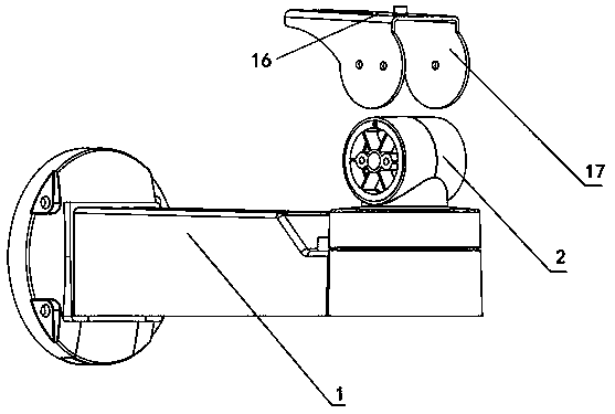
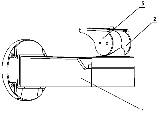
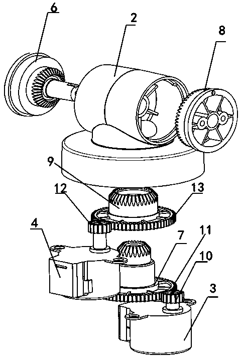
Transmission device of pan-tilt head camera

A pan-tilt camera and transmission technology, which is applied to transmissions, gear transmissions, supporting machines, etc., can solve the problems of complicated ways of controlling rotation in the up-down and left-right directions, large size of the pan-tilt, and complex structure of the transmission. The control method is simple and effective, the internal structure is compact, and the cost is reduced.

Pending Publication Date: 2019-08-23
深圳汇讯视通科技有限公司
View PDF0 Cites 3 Cited by
  • Summary
  • Abstract
  • Description
  • Claims
  • Application Information

AI Technical Summary

Problems solved by technology

This kind of structure has the problems of complex structure of the transmission device, large size of the gimb

Method used


Image

  • Transmission device of pan-tilt head camera
  • Transmission device of pan-tilt head camera
  • Transmission device of pan-tilt head camera

Examples


Example Embodiment

[0029] It should be noted that the embodiments of the present invention and the features in the embodiments can be combined with each other if there is no conflict.

[0030] In the description of the present invention, it should be understood that the terms "center", "longitudinal", "transverse", "upper", "lower", "front", "rear", "left", "right", " The orientation or positional relationship indicated by "vertical", "horizontal", "top", "bottom", "inner", "outer" etc. is based on the orientation or positional relationship shown in the drawings, and is only for the convenience of describing the present invention and The description is simplified, rather than indicating or implying that the pointed device or element must have a specific orientation, be constructed and operated in a specific orientation, and therefore cannot be understood as a limitation of the present invention. In addition, the terms "first", "second", etc. are only used for descriptive purposes, and cannot be und...


PUM


Abstract

The invention discloses a transmission device of a pan-tilt head camera. A first horizontal bevel gear and a second horizontal bevel gear are independent and coaxially arranged, so that the internal structure is more compact, and the overall size is greatly reduced; when a first motor and a second motor are same in the rotating speed and opposite in rotating direction, clockwise or anticlockwise movement of the first vertical bevel gear and the second vertical bevel gear can be realized, so that the camera fixed on a pan-tilt installing plate is driven to rotate up and down in a pitching manner; when the first motor and the second motor both the same in the rotating speed and the rotating direction, the first horizontal bevel gear and the second horizontal bevel gear rotate in the same direction, the first vertical bevel gear and the second vertical bevel gear can be in a relatively static state in the vertical direction, so that the camera fixed on the pan-tilt installing plate moveshorizontally and rotationally with respect to a pan-tilt support; and the rotation of the pitching and horizontal directions of the camera can be controlled by adjusting the rotating direction of thefirst motor and the second motor, a control mode is simple and effective, and the transmission device of the pan-tilt head camera can be applied to install a small gun type or cylindrical camera.

Description

technical field [0001] The invention relates to the technical field of video monitoring, in particular to a pan-tilt camera transmission device and a camera system. Background technique [0002] The PTZ refers to the supporting equipment for installing and fixing the camera. According to the characteristics of its rotation, the gimbal can be divided into a horizontal swivel gimbal that can only rotate left and right and an omnidirectional gimbal that can rotate both left and right and up and down; according to the adjustment method, it can be divided into two types: fixed gimbal and electric gimbal. Fixed pan / tilt refers to manual adjustment of the camera's horizontal and pitch angles, and then manually locks the adjustment mechanism after reaching the best working posture; electric pan / tilt realizes azimuth adjustment by executing the motor, and the motor receives signals from the controller to run and position accurately; The motorized pan / tilt is suitable for scanning an...

Claims


Application Information

Patent Timeline
IPC IPC(8): F16M11/12F16M11/08F16M11/10F16M11/18F16H1/22
CPCF16H1/222F16M11/08F16M11/10F16M11/123F16M11/18
Inventor 杨玉东吕增良
Owner 深圳汇讯视通科技有限公司
Why Eureka
Try Eureka