A device for testing the vibration drag reduction performance of underwater near-wall fluid
A testing device and fluid technology, which is applied in the direction of fluid dynamics test, measurement device, machine/structural component testing, etc., can solve the problem of inability to meet zero pressure gradient and variable pressure gradient test conditions, poor versatility, and difficulty in drag reduction test devices. Sealing and other issues to achieve the effect of ensuring the wall surface, reducing additional influence, and good versatility
- Summary
- Abstract
- Description
- Claims
- Application Information
AI Technical Summary
Problems solved by technology
Method used
Image
Examples
Embodiment 1
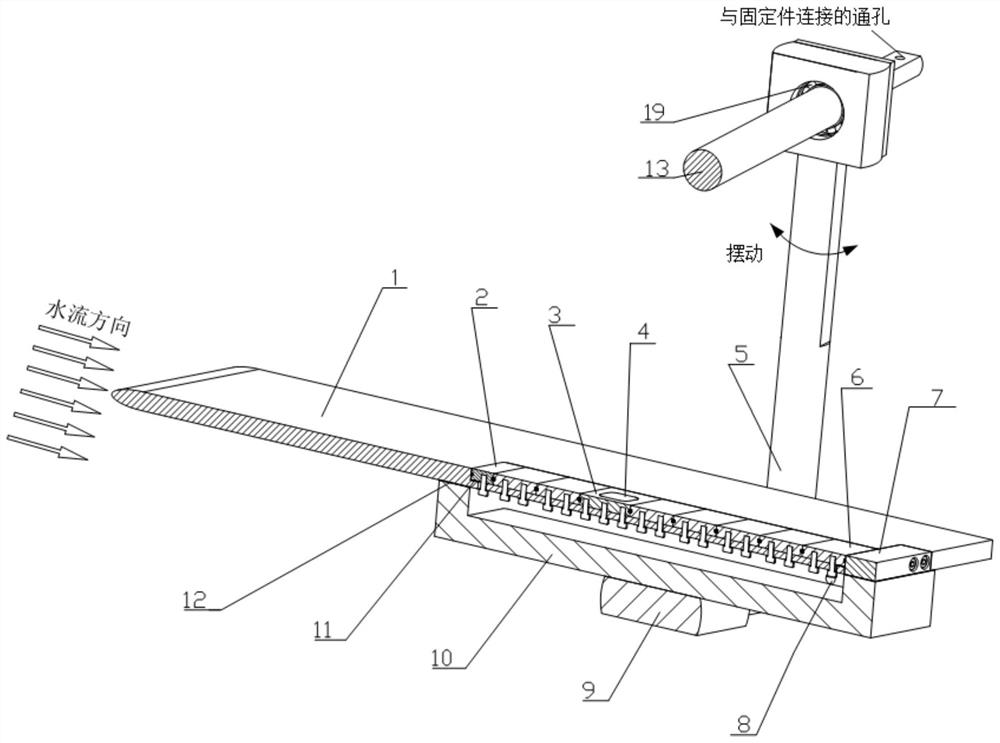
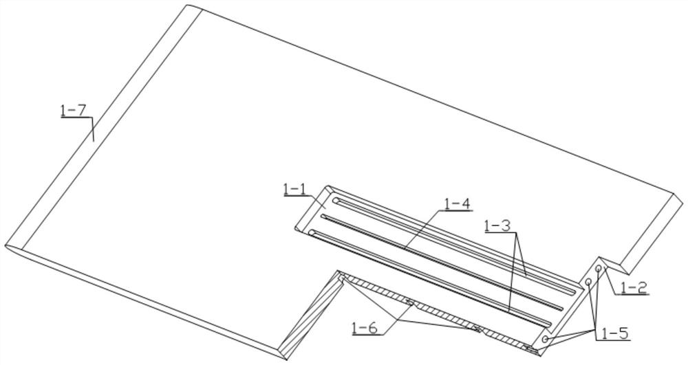
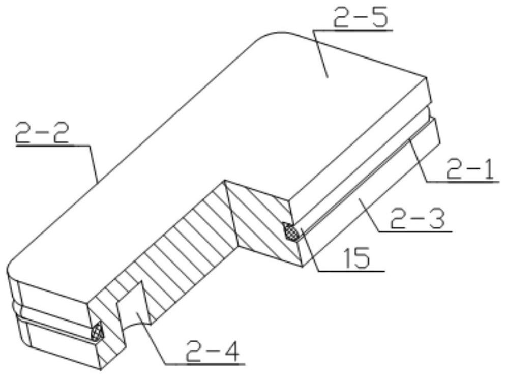
[0051] Embodiment 1: see Figure 1 to Figure 10 , an underwater near-wall fluid vibration drag reduction performance test device described in this embodiment, the test device is used for zero pressure gradient test test conditions, including a flat plate 1, a fixed block 2, a drag reducer cavity 3, a force measuring Rod 5, adjustment block 6, pressure block 7, pneumatic quick connector 8, dowel rod 9, adapter seat 10, first sealing gasket 11, second sealing gasket 12, support shaft 13, the front of the plate 1 is set There is a U-shaped groove 1-1, the fixed block 2, the drag reducer cavity 3, and the adjusting block 6 are placed in the U-shaped groove 1-1 along the flow direction, and the right end of the plate 1 is provided with The positioning groove 1-2, the pressing block 7 is fixed in the positioning groove 1-2 by screws, and the fixing block 2, the drag reducer cavity 3, and the adjusting block 6 are pressed in the flow direction Tight, the bottom of the U-shaped groov...
Embodiment 2
[0060] Example 2: see Figure 2 to Figure 4 , Figure 6 , Figure 7 , Figure 9 to Figure 13 , an underwater near-wall fluid vibration drag reduction performance test device described in this embodiment, the test device is used for the test conditions of the variable pressure gradient test, including a flat plate 1, a fixed block 2, a drag reducer cavity 3, and an adjustment block 6. Briquetting block 7, pneumatic quick connector 8, adapter seat 10, first sealing gasket 11, second sealing gasket 12, supporting shaft 13, supporting force measuring rod 18, and a U-shaped groove is opened on the front of the plate 1 1-1, the fixed block 2, the drag reducer cavity 3, and the adjustment block 6 are placed in the U-shaped groove 1-1 along the flow direction, and the right end of the plate 1 is provided with a positioning groove 1- 2. The pressing block 7 is fixed in the positioning groove 1-2 by screws, and the fixing block 2, the drag reducer cavity 3, and the adjusting block 6 ...
PUM
 Abstract
Description
Claims
Application Information
 - R&D
- Intellectual Property
- Life Sciences
- Materials
- Tech Scout
- Unparalleled Data Quality
- Higher Quality Content
- 60% Fewer Hallucinations
Browse by: Latest US Patents, China's latest patents, Technical Efficacy Thesaurus, Application Domain, Technology Topic, Popular Technical Reports.
© 2025 PatSnap. All rights reserved.Legal|Privacy policy|Modern Slavery Act Transparency Statement|Sitemap|About US| Contact US: help@patsnap.com


