Method of warning rear vehicle due to emergency stop on highway and system

A technology for rear vehicles and highways, which is applied to the traffic control system, anti-collision system, signal transmission system, etc. of road vehicles to achieve the effect of large safety factor and high alarm efficiency.

Inactive Publication Date: 2019-08-23
HUIZHOU DESAY SV INTELLIGENT TRANSPORTATION TECH INST CO LTD
View PDF5 Cites 0 Cited by
  • Summary
  • Abstract
  • Description
  • Claims
  • Application Information

AI Technical Summary

Problems solved by technology

[0005] The purpose of the present invention is to solve the problem that when a vehicle needs to stop in an emergency at any time due to a sudden failure or an emergency, the driver does not

Method used


Image

  • Method of warning rear vehicle due to emergency stop on highway and system
  • Method of warning rear vehicle due to emergency stop on highway and system
  • Method of warning rear vehicle due to emergency stop on highway and system

Examples


Embodiment 1

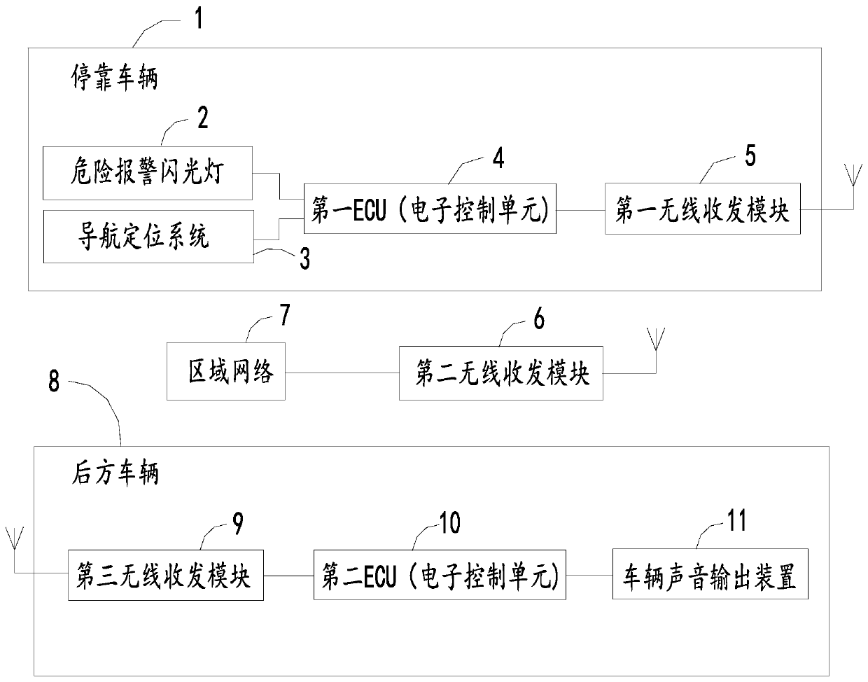
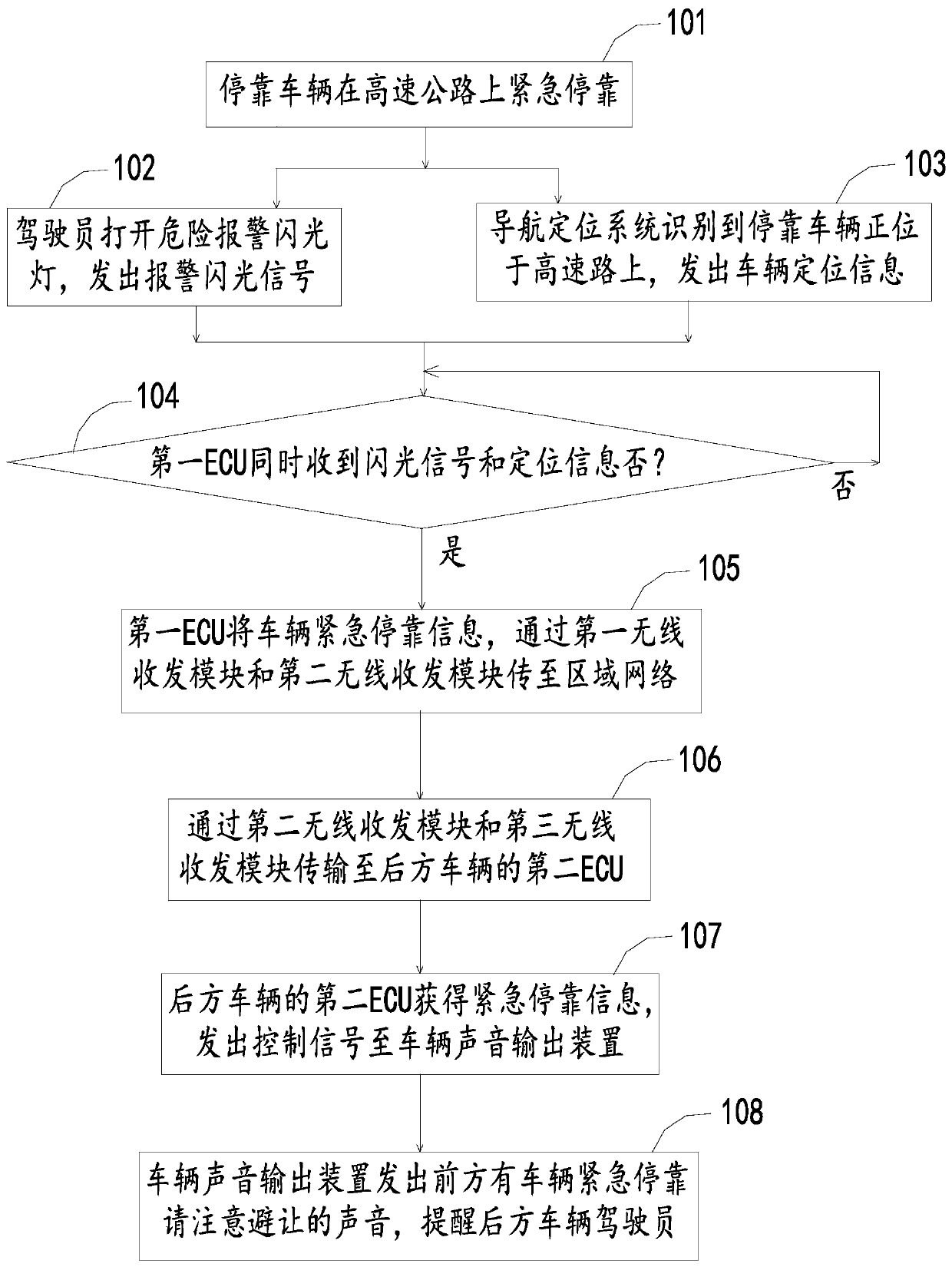
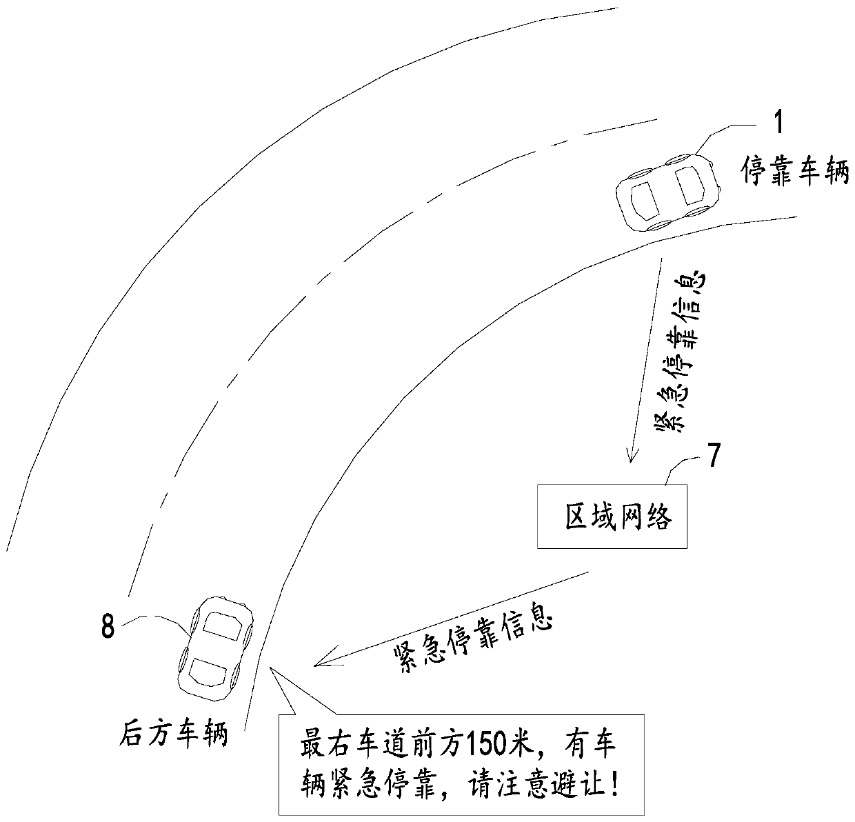
[0044] Such as figure 1 As shown, a system for emergency parking on the expressway to warn rear vehicles includes an emergency parking vehicle 1, a hazard warning flashlight 2 on the parked vehicle 1, a navigation and positioning system 3, and simultaneously with the danger warning flashlight 2 and the navigation and positioning system 3 The first ECU electrically connected (ECU is the comprehensive writing of Electronic Control Unit, the Chinese is electronic control unit, also known as "driving computer" or "vehicle computer") 4, and the first wireless transceiver module 5 electrically connected to the first ECU 4 .

[0045]It also includes a second wireless transceiver module 6 wirelessly connected to the first wireless transceiver module 5 and an area network 7 electrically connected to the second wireless transceiver module 6 . Also comprise the rear vehicle 8 that is positioned at the parking vehicle 1 rear, the third wireless transceiver module 9 that is wirelessly con...

Embodiment 2

[0059] Such as Figure 4 As shown, a system for emergency parking on the expressway to warn rear vehicles includes an emergency parking vehicle 1, a hazard warning flashlight 2 on the parked vehicle 1, and a navigation and positioning system 3, which are simultaneously connected with the hazard warning flashlight 2 and the navigation and positioning system 3. The first ECU 4 electrically connected, and the first wireless transceiver module 5 electrically connected to the first ECU 4 . Also comprise the rear vehicle 8 that is positioned at the parking vehicle 1 rear, the rear vehicle 8 includes the 3rd wireless transceiver module 9 that is wirelessly connected with the first wireless transceiver module 5, the second ECU 10 that is electrically connected with the 3rd wireless transceiver module 9, and The vehicle sound output device 11 to which the second ECU 10 is electrically connected.

[0060] Specifically, the first ECU 4 receives the flash signal of the danger warning fla...


PUM


Abstract

The invention relates to a system for warning a rear vehicle due to emergency stop on a highway, which comprises an emergency stop vehicle, a danger alarm flashing light and a navigation and positioning system on the stop vehicle, a first ECU electrically connected with the danger alarm flashing light and the navigation and positioning system, a first wireless transceiver module electrically connected with the first ECU, a second wireless transceiver module wirelessly connected with the first wireless transceiver module, a regional network electrically connected with the second wireless transceiver module and a rear vehicle located behind the stop vehicle, wherein the rear vehicle is provided with a third wireless transceiver module wirelessly connected with the second wireless transceivermodule, a second ECU electrically connected with the third wireless transceiver module, and a vehicle sound output device electrically connected with the second ECU. A driver does not need to risk setting a warning sign, the safety of all rear vehicles can also be ensured, early warning is achieved, the alarm efficiency is high, the safety factor is large, and the method and the system can adaptto various environments and are not affected by climate changes.

Description

technical field [0001] The invention relates to the field of driving safety, in particular to a method and system for emergency parking on expressways to warn vehicles behind. Background technique [0002] With the development of the automobile industry and the rapid construction of expressways, road and driving safety issues have become increasingly prominent. Although some detection devices related to driving safety have been installed in individual areas, it is far from being able to solve the possibility that vehicles need to stop at any time due to sudden failures or emergencies. More vehicles in the rear get the information as early as possible, and should take early avoidance measures to ensure driving safety. [0003] The problem exposed now is: when a vehicle breaks down on the expressway or needs to stop urgently due to an emergency, not only must the warning lights be turned on, but also warning signs need to be placed at a certain distance, and placing signs man...

Claims


Application Information

Patent Timeline
IPC IPC(8): G08G1/09G08B5/38G08C17/02G08B21/24G08B7/06G08G1/16
CPCG08B5/38G08B7/06G08B21/24G08C17/02G08G1/09G08G1/166
Inventor 刘鹏曾婕
Owner HUIZHOU DESAY SV INTELLIGENT TRANSPORTATION TECH INST CO LTD
Why Eureka
Try Eureka