Distal humerus osteotomy orthopedic percutaneous navigation device and operating method thereof
A navigation device and humerus technology, which is applied in the field of medical devices, can solve problems such as difficulty in reaching the ideal position, and achieve the effects of precise guidance, less simulated bleeding, and low iatrogenic damage
- Summary
- Abstract
- Description
- Claims
- Application Information
AI Technical Summary
Problems solved by technology
Method used
Image
Examples
Embodiment 1
[0043]Embodiment one, such as Figure 1 to Figure 10 as shown,
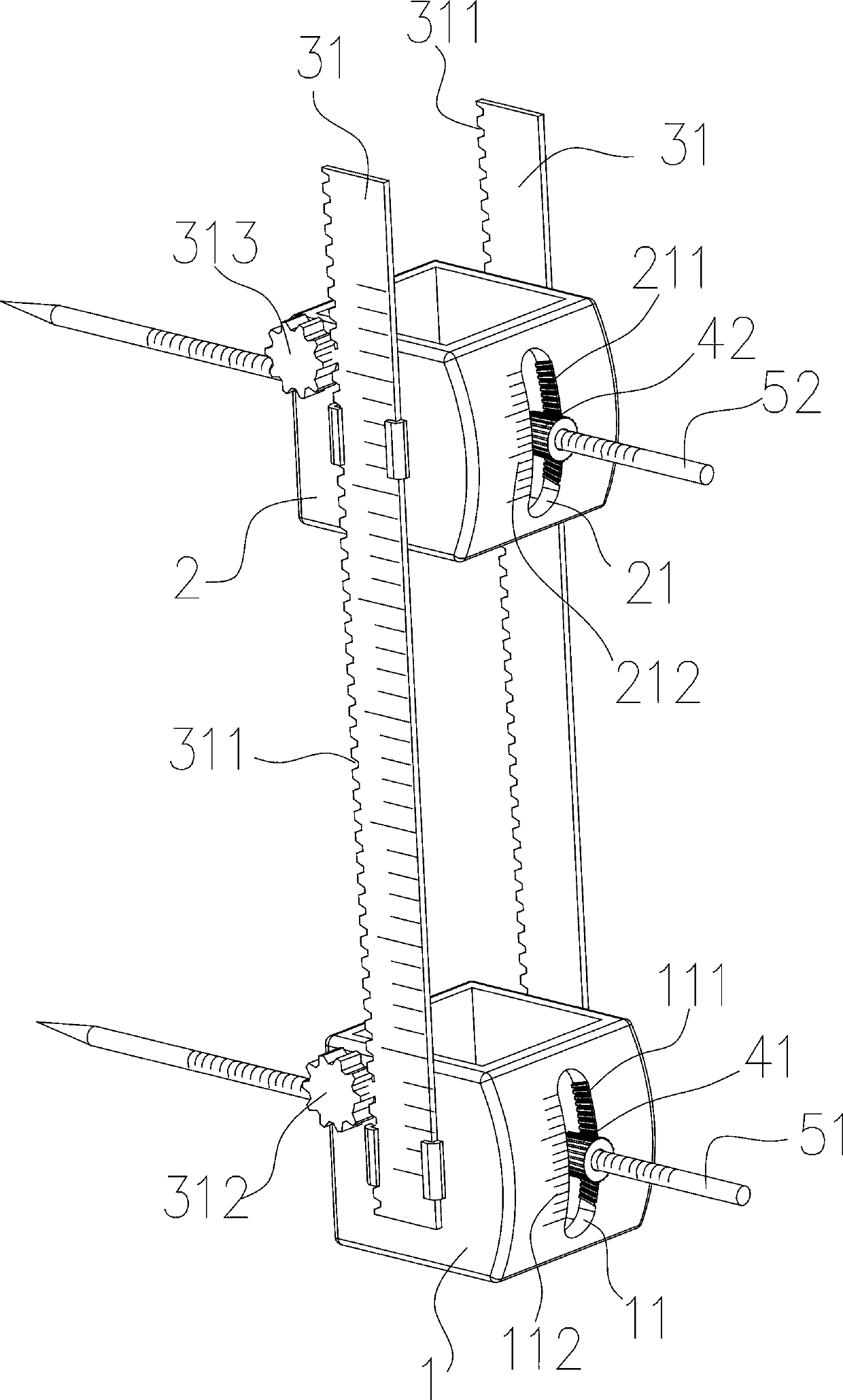
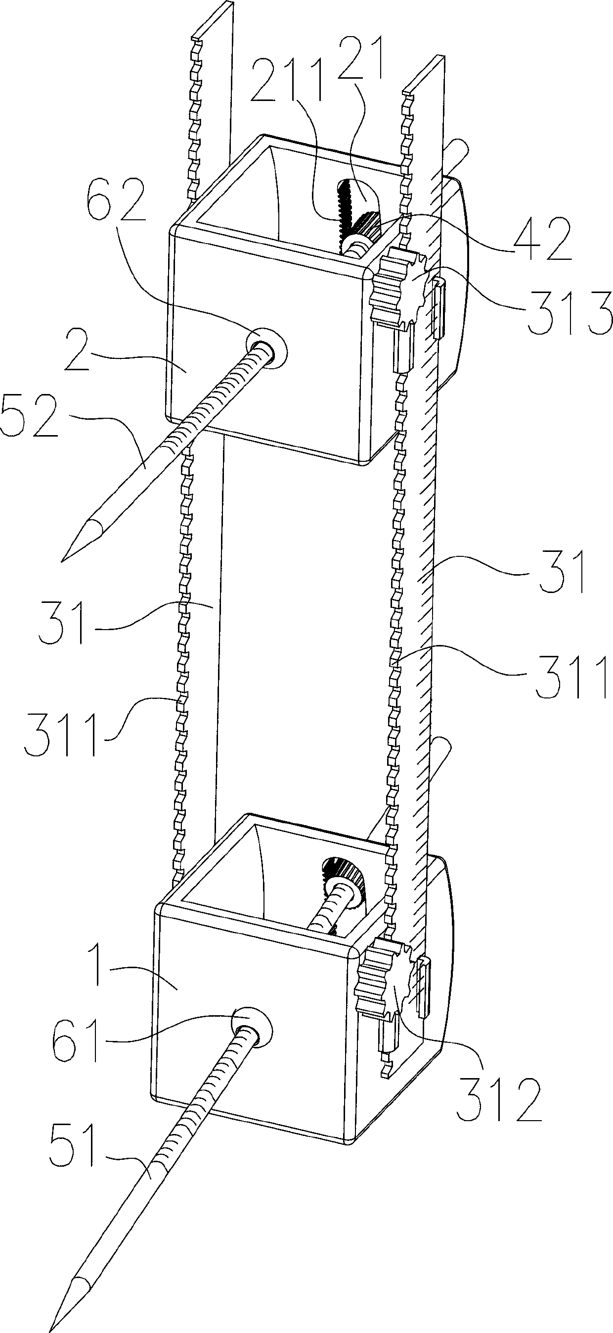
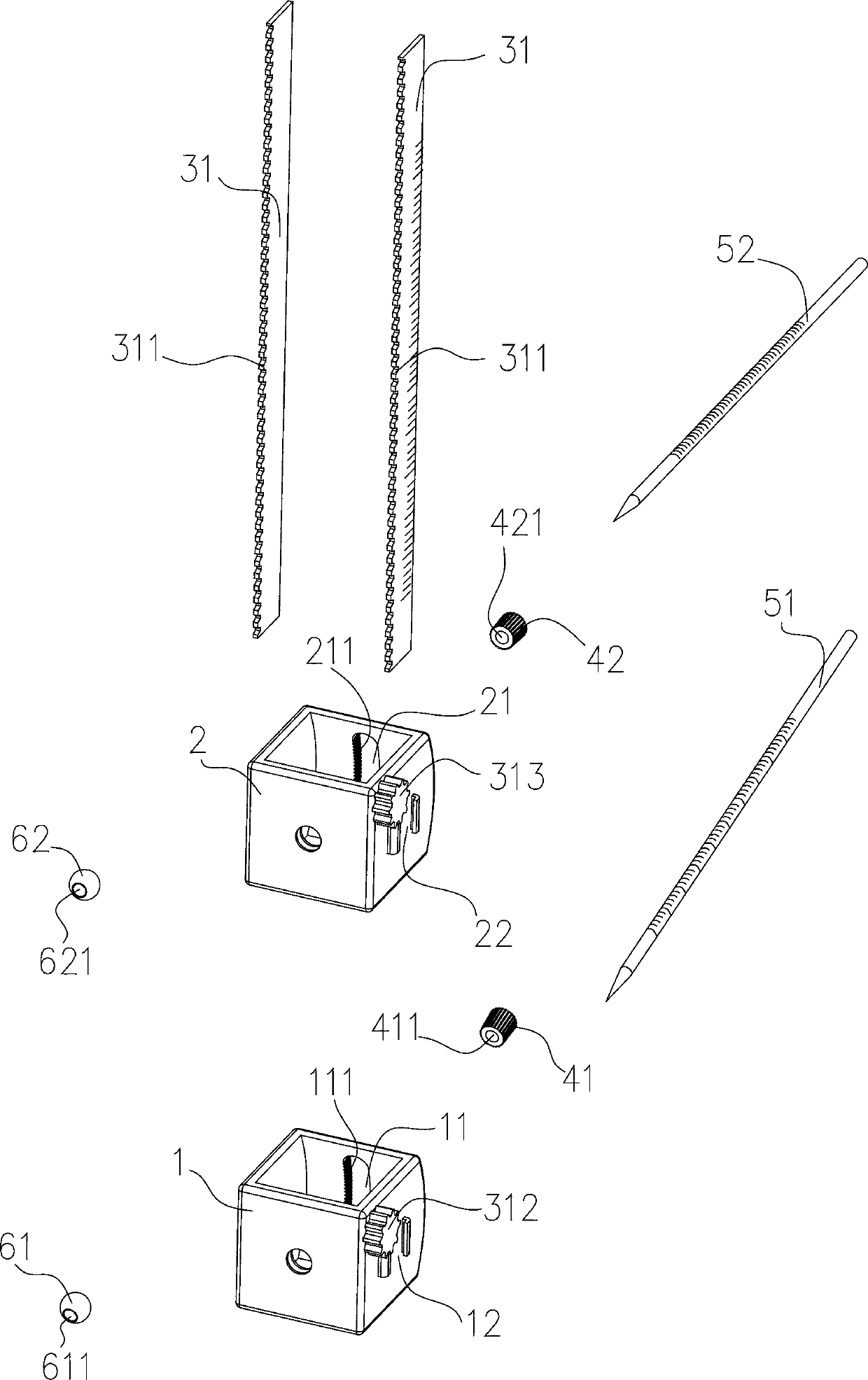
[0044] A percutaneous navigation device for distal humerus osteotomy correction, comprising a first steel needle group 51 vertically fixed on the humerus distal body segment 73 and a second steel needle group 52 vertically fixed on the humerus proximal body segment 71, the first steel needle group The group 51 is perpendicular to the mechanical axis of the far body section 73, and the second steel needle 52 group is perpendicular to the mechanical axis of the proximal section 71; it also includes the first seat body 1 and the second seat body 2 arranged side by side along the length direction of the humerus, the first seat body The body 1 is provided with the first support member 61 as the swing fulcrum of the first steel needle group 51, and the first seat body 1 is provided with a first angle scale line 112 in the swing stroke of the first steel needle group 51, and the second seat body 2 There is a second sup...
Embodiment 2
[0050] Embodiment two, such as Figure 11 and Figure 12 as shown,
[0051] The structure of the second embodiment is similar to that of the first embodiment, the difference is that the movable joint includes a first bolt 32 which is arranged on the second seat body 2 in the circumferential direction, and a first bolt 32 which is arranged on the first seat body 1 in the circumferential direction. Two bolts 33 , the first base body 1 is provided with a first threaded hole 13 threaded with the first bolt 32 , and the second seat body 2 is provided with a second threaded hole 23 threaded with the second bolt 33 . Rotating the first bolt 32 can make the first seat 1 move toward the second seat 2, and rotating the second bolt 33 can make the second seat 2 move toward the first seat 1. The first bolt 32 and the second The bolts 33 have the same structure, and usually the first bolt 32 and the second bolt 33 are rotated synchronously during use, which can prevent the whole device f...
Embodiment 3
[0052] Embodiment three, such as Figure 13 , 14 and Figure 15 as shown,
[0053] The structure of the third embodiment is similar to that of the second embodiment, except that the first toggle piece 41 and the second toggle piece 42 are sliders respectively, and the first toggle piece 41 is temporarily fixed to the first seat body 1. The first temporary positioning device; the second toggle member 42 is provided with a second temporary positioning device temporarily fixed on the second seat body 2 .
[0054] In the embodiment, the first temporary positioning device includes a first stud 412 arranged on the first toggle member 41, and a first nut 413 screwed on the first stud 412, and one end of the first nut 413 is set On the first seat body 1; the second temporary positioning device includes a second stud 422 arranged on the second toggle 42, and a second nut 423 screwed on the second stud 422, the second nut 423 One end is set on the second base body 2 . Rotate the fi...
PUM
 Abstract
Description
Claims
Application Information
 - R&D
- Intellectual Property
- Life Sciences
- Materials
- Tech Scout
- Unparalleled Data Quality
- Higher Quality Content
- 60% Fewer Hallucinations
Browse by: Latest US Patents, China's latest patents, Technical Efficacy Thesaurus, Application Domain, Technology Topic, Popular Technical Reports.
© 2025 PatSnap. All rights reserved.Legal|Privacy policy|Modern Slavery Act Transparency Statement|Sitemap|About US| Contact US: help@patsnap.com


