
Devices and methods for manufacturing hairpin winding

A hairpin and winding technology, applied in the manufacture of motor generators, prefabricated windings embedded in motors, electromechanical devices, etc., can solve problems such as insulation difficulties

Active Publication Date: 2019-08-23
ZF FRIEDRICHSHAFEN AG
View PDF11 Cites 0 Cited by
  • Summary
  • Abstract
  • Description
  • Claims
  • Application Information

AI Technical Summary

Problems solved by technology

[0003] A problem with the prior art is especially the block-like positioning of the contact ends, since this makes it difficult to insulate the different lines of the hairpin winding from one another and conduction can occur between the different lines of the hairpin winding. touch

Method used


Image

  • Devices and methods for manufacturing hairpin winding
  • Devices and methods for manufacturing hairpin winding
  • Devices and methods for manufacturing hairpin winding

Examples


Embodiment Construction

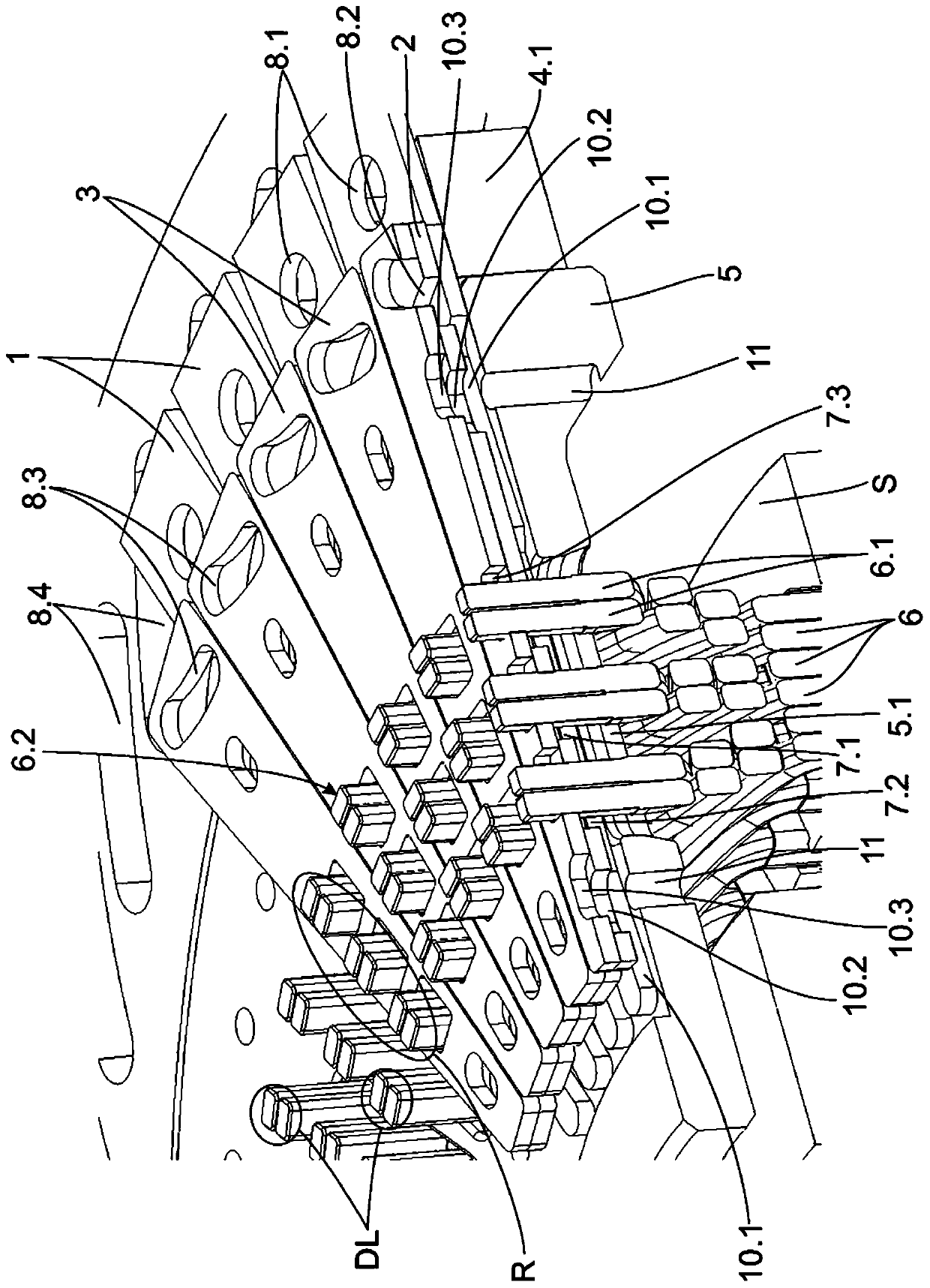
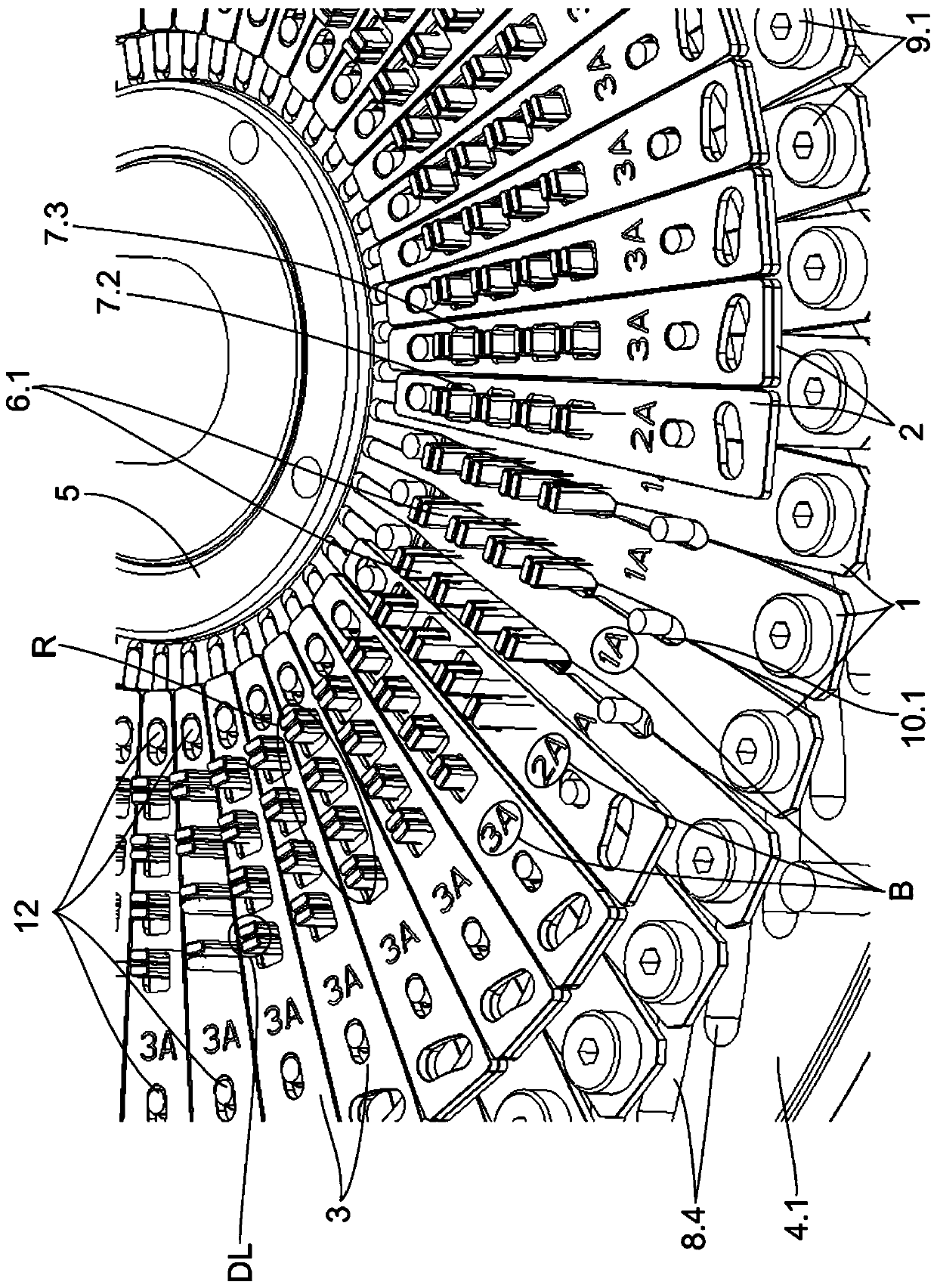
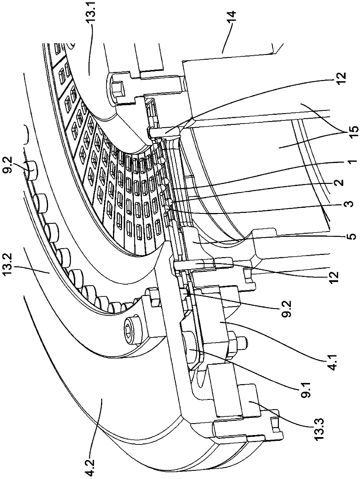
[0036] figure 1 A part of an element according to an embodiment of the invention during application is shown, ie a device with a contact end 6.1 of a hairpin 6 placed to a winding of an electric machine (here a stator S). For better illustration, not all parts of the device are shown.

[0037] The device has a plurality of first orientation elements 1 which are wedge-shaped and are arranged in each case between the arrangement R formed by the contact ends 6.1. A first plane is formed by the first alignment elements 1 arranged next to each other in the circumferential direction, which in the embodiment shown lies on the support plate 5 . Between the first orientation elements 1 there is provided an opening 7.1, which is located along the side facing the contact end 6.1. In the example shown, the opening 7 . 1 is formed by a wedge-shaped taper between the two first alignment elements 1 . By moving the first alignment elements 1 in the radial direction towards the center, the ...


PUM


Abstract

The invention relates to a device and a method for manufacturing a hairpin winding. The invention specially relates to a device and a method for orienting contact ends (6.1) of a hairpin (6) of a hairpin winding, wherein the contact ends of the hairpin winding are arranged in a double-layer (DL) extending in the circumferential direction and in a radially extending arrangement (R) in the number corresponding to the number of slots; the device comprises orientation elements (1, 2, 3) which can move relative to one another, wherein at least one part of the elements has an opening (7.1, 7.2, 7.3), openings are oriented relative to one another in such a way that they are oriented, therefore, the contact ends can pass through; a plurality of first orientation elements (1) for the tangential orientation of the contact end are provided, a plurality of second and third orientation elements 2, 3 for the radial orientation of the contact ends are provided, each of which has at least two openings(7.2, 7.3) for receiving an arrangement of contact ends in accordance with the number of double-layers, and which can be moved differently in the radial direction.

Description

technical field [0001] The invention relates to a device and a method for orienting the ends of hairpins to be connected to each other during the production of hairpin windings for electrical machines. Background technique [0002] It is known in the prior art, for example from document WO 2012 / 119691 A1, in which the orientation of the ends of the hairpins is carried out by means of two disks which are rotatable relative to each other and which have recesses, wherein the contact ends of the hairpins are The parts are pushed together to form a block, whereby the positioning of the contact ends takes place. [0003] A problem with the prior art is especially the block-like positioning of the contact ends, since this makes it difficult to insulate the different lines of the hairpin winding from one another and conduction can occur between the different lines of the hairpin winding. touch. Contents of the invention [0004] The object of the present invention is to provide ...

Claims


Application Information

Patent Timeline
Patent Type & Authority Applications(China)
IPC IPC(8): H02K15/00
CPCH02K15/0087H02K15/00H02K15/06H02K15/0081H01F41/10
Inventor A·格吕贝尔J·特勒斯特M·艾伯特
Owner ZF FRIEDRICHSHAFEN AG
Learn More