
Cantilevered x-ray ct system for multi-axis imaging

An imaging system, imaging technology, applied in the fields of radiological diagnosis instruments, X-ray/γ-ray/particle irradiation therapy, applications, etc., can solve problems such as type restrictions

Pending Publication Date: 2019-08-23
MOBIUS IMAGING
View PDF7 Cites 7 Cited by
  • Summary
  • Abstract
  • Description
  • Claims
  • Application Information

AI Technical Summary

Problems solved by technology

[0003] Conventional medical imaging devices, such as x-ray computed tomography (CT) imaging devices, are limited in the types of imaging operations that can be performed

Method used


Image

  • Cantilevered x-ray ct system for multi-axis imaging
  • Cantilevered x-ray ct system for multi-axis imaging
  • Cantilevered x-ray ct system for multi-axis imaging

Examples


Embodiment Construction

[0022] This application is related to U.S. Application No. 13 / 916,869, filed June 13, 2013, and to U.S. Application No. 15 / 685,955, filed August 24, 2017, both of which are set forth in their entirety as Incorporated herein by reference.

[0023] Various embodiments will be described in detail with reference to the accompanying drawings. Wherever possible, the same reference numbers will be used throughout the drawings to refer to the same or like parts. References made to particular examples and implementations are for illustrative purposes, and are not intended to limit the scope of the invention or the claims.

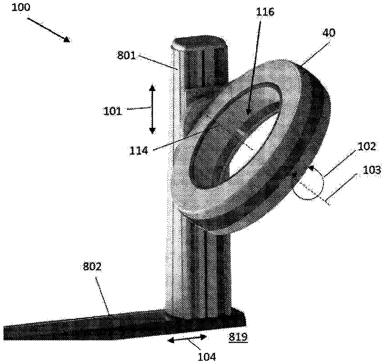
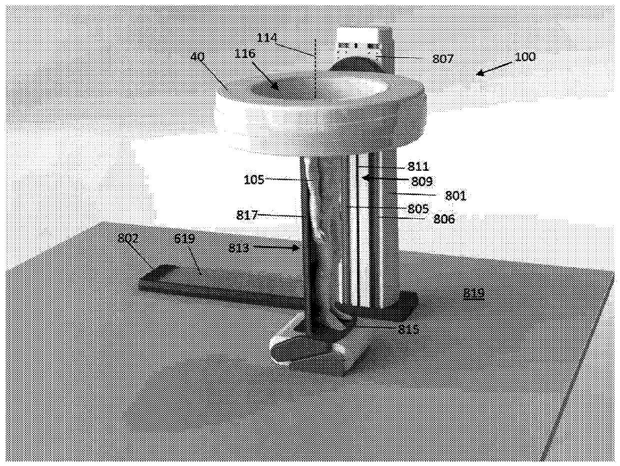
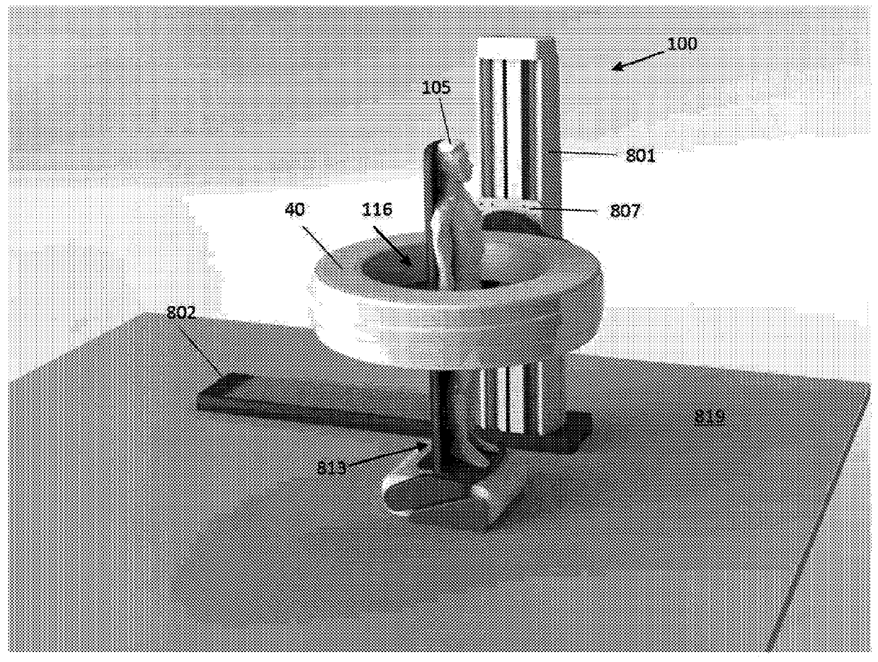
[0024] see figure 1 , shows an imaging system 100 according to an embodiment of the present invention. System 100 includes an image collection assembly, such as a rotating x-ray source and detector array, a rotating gamma ray camera, or a stationary magnetic resonance imaging assembly, housed within gantry 40 . The system 100 is configured to collect imaging da...


PUM


Abstract

A multi-axis imaging system and methods for imaging a human or animal using a multi-axis imaging system are provided.

Description

[0001] Related applications [0002] This application claims the benefit of priority to U.S. Provisional Application No. 62 / 425,746, filed November 23, 2016, and U.S. nonprovisional application Serial No. 15 / 817,672, filed November 20, 2017, which The entire contents of the application are incorporated herein by reference. Background technique [0003] Conventional medical imaging devices, such as x-ray computed tomography (CT) imaging devices, are limited in the types of imaging operations that can be performed. Contents of the invention [0004] Embodiments include multi-axis imaging systems and methods for imaging a human or animal using the multi-axis imaging systems. [0005] Various embodiments include a multi-axis imaging system comprising: an imaging gantry; a support column supporting the imaging gantry in a cantilever fashion on one side of the gantry; a base supporting the imaging gantry and the support column; a first drive mechanism that translates the frame ...

Claims


Application Information

Patent Timeline
IPC IPC(8): A61B6/00A61B6/03
CPCA61B6/03A61B6/487A61B6/547A61B6/027A61B6/102A61B6/4085A61B6/037A61B6/0407A61B6/4447A61B6/508A61B6/035A61B6/4405A61N2005/1061A61B6/0487A61B6/4476B25J19/0075A61B6/505A61B6/504A61B6/4458B25J15/0019B25J5/02B25J9/104B25J9/1676B25J9/0096A61B6/00A61B5/055
Inventor E·A·格雷格森R·斯坦顿M·康纳P·西布林
Owner MOBIUS IMAGING
Learn More