
Intelligent cabinet

A cabinet and intelligent technology, applied in the field of cabinets, can solve the problems of surface corrosion of the inner partition and deformation of the pressure-bearing slide rail of the bowl rail rack, so as to increase the stress point, reduce the possibility of damage and deformation, and improve the stability. sexual effect

Active Publication Date: 2019-08-27
广东亿科不锈钢制品有限公司
View PDF7 Cites 4 Cited by
  • Summary
  • Abstract
  • Description
  • Claims
  • Application Information

AI Technical Summary

Problems solved by technology

[0006] The present invention can solve the problem that the lower end of the existing bowl rack is a hollow mesh structure, which facilitates the dripping of residual water droplets on the bowls and chopsticks. The dripping water droplets often drip on the inner partitions of the cabinets, and personnel need to periodically clean the surface of the inner partitions. However, it is difficult to wipe the dead corners, and the water droplets remaining in the dead corners will easily cause the surface of the inner partition to be corroded, and a large number of bacteria often breed in a humid environment. The existing bowl rails are connected to the inner wall of the cabinet through slide rails When the bowl rack is pulled to the front end, the force point of the bowl rack is concentrated at the rear end. Due to the heavy weight of the bowl rack and the bowls and chopsticks, the greater pressure of the bowl rack will easily lead to slippage. Rail deformation and other issues

Method used


Image

  • Intelligent cabinet
  • Intelligent cabinet
  • Intelligent cabinet

Examples


Embodiment Construction

[0034] Embodiments of the present invention will be described below with reference to the drawings. In the process, in order to ensure the clarity and convenience of illustration, we may exaggerate the width of the lines or the size of the constituent elements in the diagram.

[0035] In addition, the following terms are defined based on the functions in the present invention, and may be different according to the user's or operator's intention or practice. Therefore, these terms are defined based on the entire content of this specification.

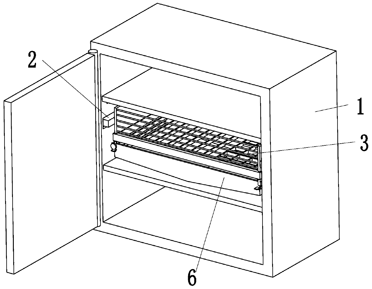
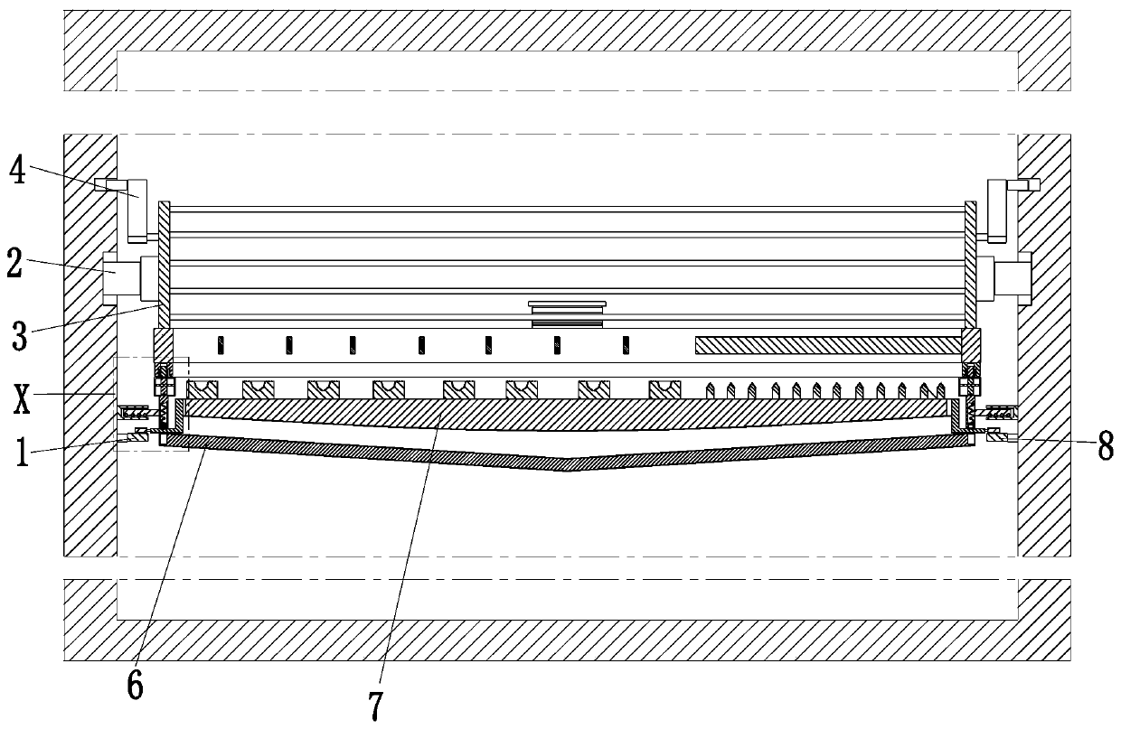
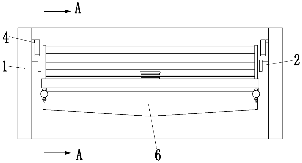
[0036] Such as Figure 1 to Figure 7 As shown, a smart cabinet includes a storage frame 1, an electric slider 2, a bowl rail 3, a stable frame 4, a tension plate 5, a locking water collection frame 6, a splash-proof sponge 7 and an extrusion track 8 , the middle side wall of the storage frame 1 is symmetrically installed with electric sliders 2 left and right, the electric slider 2 is provided with a bowl railing 3, and the left and ri...


PUM


Abstract

The invention relates to an intelligent cabinet. The intelligent cabinet comprises a storage frame, electric sliding blocks, bowl pulling bar frames, stabilizing frames, tensioning plates, fastening water collecting frames, splash-proof sponges and extruding rails, the electric sliding blocks are mounted on the side wall of the middle of the storage frame in a left-right symmetric mode, the electric sliding blocks are provided with the bowl pulling bar frames, the stabilizing frames are mounted at the left ends and the right ends of the bowl pulling bar frames, the rear ends of the bowl pulling bar frames are connected with the inner wall of the storage frame through the tensioning plates, the fastening water collecting frames are arranged at the lower ends of the bowl pulling bar frames,the splash-proof sponges are arranged in the fastening water collecting frames, and the extruding rails are arranged on the lower parts of the electric sliding blocks. According to the intelligent cabinet, the lower ends of the bowl pulling bar frames are of hollow out net-shaped structures, dropping of residual water droplets on bowls and chopsticks is convenient, the surface of an inner separation plate is scrubbed by personnel at fixed period, but dead corners are difficult to scrub, and problem that the surface of the inner separation plate is prone to being corroded due to the water droplets residual remaining at the dead corners is prone to occurring.

Description

technical field [0001] The invention relates to the field of cabinets, in particular to an intelligent cabinet. Background technique [0002] Cabinet refers to the platform for storing kitchen utensils and cooking operations in the kitchen. People can put kitchen utensils and kitchen utensils in so as to achieve the benefit of saving space, and it is convenient for people to search for the second time. When placing bowls and chopsticks, you need to use the bowl bar The personnel usually pull out the bowl rack and put the bowls and chopsticks in order. However, the existing bowl racks often encounter the following problems: [0003] 1. The lower end of the bowl rack is a hollow mesh structure, which facilitates the dripping of residual water droplets on the bowls and chopsticks. The dripping water droplets often drip on the inner partition of the cabinet. Personnel need to wipe the surface of the inner partition regularly, but , it is difficult to wipe the dead corners, and ...

Claims


Application Information

Patent Timeline
Patent Type & Authority Applications(China)
IPC IPC(8): A47B77/02A47B96/06
CPCA47B77/022A47B96/06A47B2077/025
Inventor 解甜陈国瑜
Owner 广东亿科不锈钢制品有限公司
Learn More