Tensioning structure based on main shaft

A spindle and claw technology, applied in the field of CNC high-speed machining equipment, can solve the problems of insufficient rigidity and poor clamping stability, and achieve the effect of improving clamping accuracy, stable clamping and high rigidity

Pending Publication Date: 2019-08-27
深圳市爱贝科精密工业股份有限公司
View PDF0 Cites 4 Cited by
  • Summary
  • Abstract
  • Description
  • Claims
  • Application Information

AI Technical Summary

Problems solved by technology

[0004] The purpose of the present invention is to provide a tensioning structure based on the main shaft, so as to solve the problem of poor stability and insufficient rigidity when clamping the tool proposed by the above-mentioned background technology

Method used


Image

  • Tensioning structure based on main shaft
  • Tensioning structure based on main shaft

Examples


Embodiment Construction

[0019] The following will clearly and completely describe the technical solutions in the embodiments of the present invention with reference to the accompanying drawings in the embodiments of the present invention. Obviously, the described embodiments are only some of the embodiments of the present invention, not all of them. Based on the embodiments of the present invention, all other embodiments obtained by persons of ordinary skill in the art without making creative efforts belong to the protection scope of the present invention.

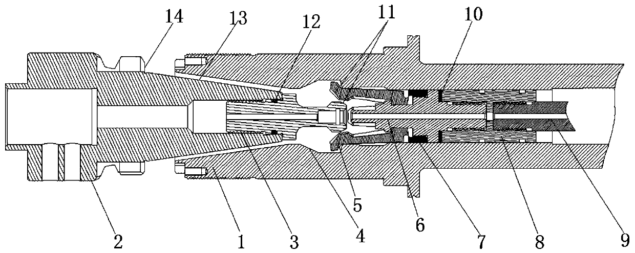
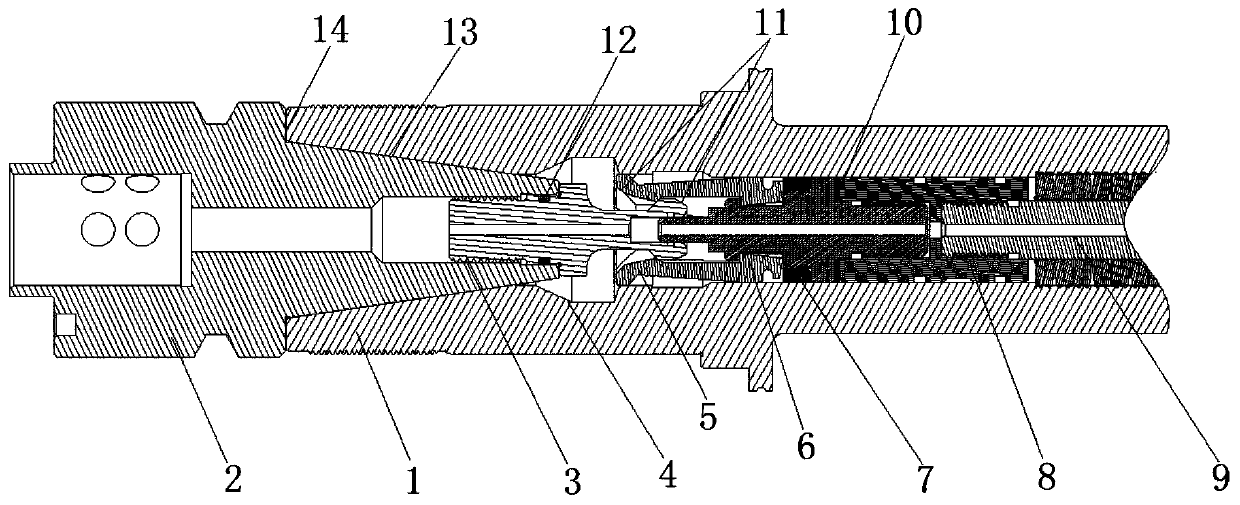
[0020] see Figure 1-2 , the present invention provides a technical solution: a tensioning structure based on the main shaft, including a rotor 1, a knife handle mechanism and a claw mechanism, the knife handle mechanism includes a knife handle 2, a pull nail 3 and a sealing ring 12, and the knife handle 2 is inserted Connected to the outside of the rotor 1, the side of the handle 2 close to the rotor 1 is provided with a tapered surface 13, and ...


PUM


Abstract

The invention discloses a tensioning structure based on a main shaft. The tensioning structure comprises a rotor, a tool holder mechanism and a pulling claw mechanism, the tool holder mechanism comprises a tool holder, a pulling nail and a sealing ring, the tool holder is connected into the outer side of the rotor in an inserted mode, and a conical surface is arranged on the side, close to the rotor, of the tool holder. According to the tensioning structure based on the main shaft, in the tool clamping process, the conical surface of the tool holder is preferentially attached to a conical opening in the rotor, then the inner wall of the conical opening of the rotor is deformed and opened when the tool holder continues to move backwards, meanwhile, the end surface on the tool holder is tightly attached to a port on the rotor, the conical surface and the end surface of the tool holder both make close contact with the rotor, so that the main shaft has higher radial and axial rigidity, sothat the tool holder is clamped more stably, and the precision of a part and the flatness and the smoothness of the plane can be improved.

Description

technical field [0001] The invention relates to the technical field of CNC high-speed machining equipment, in particular to a tensioning structure based on a spindle. Background technique [0002] CNC high-speed machining equipment usually refers to CNC milling machine equipment, and the spindle box on the CNC milling machine is used to clamp the tool and drive the tool to rotate, while the spindle speed range and output torque have a direct impact on processing. [0003] At present, for the BT30 handle, there are some deficiencies in the installation and removal. When the tool is actually clamped, only the tapered surface of the tool handle is in close contact with the rotor, resulting in poor stability. The main reason is that the rigidity after the combination is insufficient. Contents of the invention [0004] The purpose of the present invention is to provide a tensioning structure based on the main shaft, so as to solve the problems of poor stability and insufficien...

Claims


Application Information

Patent Timeline
Patent Type & Authority Applications(China)
IPC IPC(8): B23B19/02B23Q3/12
CPCB23Q1/70B23Q3/12
Inventor 农乃昌李存杰
Owner 深圳市爱贝科精密工业股份有限公司
Why Eureka
Try Eureka