A non-contact gas wiping galvanizing device for steel wire

A non-contact, gas technology, applied in hot dip plating process, coating, metal material coating process, etc., can solve the problem of easy deviation of the position of the steel wire and the air knife, difficult to adjust, etc., to enhance the wiping effect and quality , The effect of keeping the conveying smooth and convenient for disassembly and installation

Active Publication Date: 2021-06-15
河间市宝泽龙金属材料有限公司
View PDF0 Cites 0 Cited by
  • Summary
  • Abstract
  • Description
  • Claims
  • Application Information

AI Technical Summary

Problems solved by technology

[0003] The invention proposes a steel wire non-contact gas wiping galvanizing device, which solves the problem that the position of the steel wire and the air knife is easily deviated and difficult to adjust in the prior art

Method used


Image

  • A non-contact gas wiping galvanizing device for steel wire
  • A non-contact gas wiping galvanizing device for steel wire
  • A non-contact gas wiping galvanizing device for steel wire

Examples


Embodiment Construction

[0058] The technical solutions in the embodiments of the present invention will be clearly and completely described below in conjunction with the embodiments of the present invention. Apparently, the described embodiments are only some of the embodiments of the present invention, not all of them. Based on the embodiments of the present invention, all other embodiments obtained by persons of ordinary skill in the art without creative efforts fall within the protection scope of the present invention.

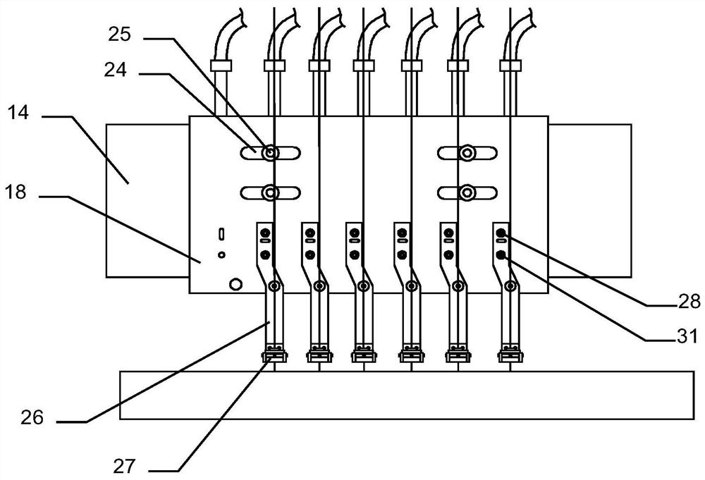
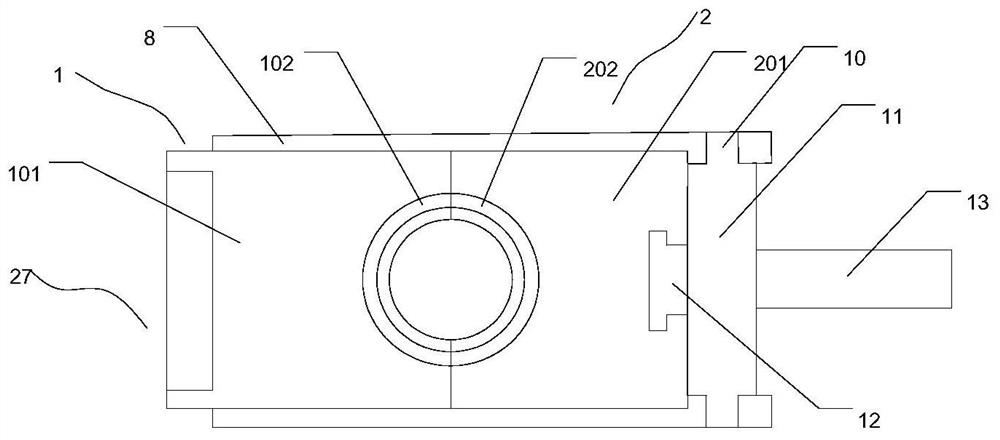
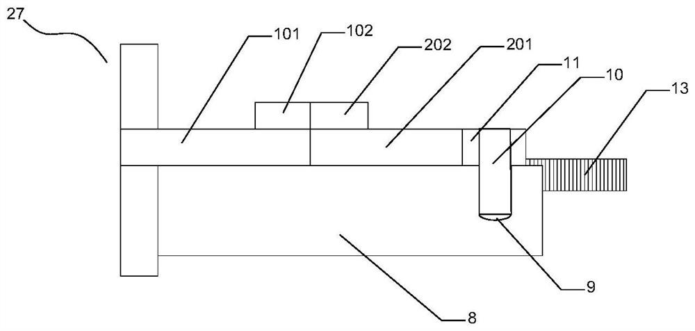
[0059] like Figure 1-Figure 7 As shown, the present invention proposes a steel wire non-contact gas wiping galvanizing device,

[0060] including the fixing frame 14,

[0061] Gas-collecting box 18, strip-shaped through-holes 24 are arranged on the opposite sides of the gas-collecting box 18 along the transverse direction, and the edges of the two strip-shaped through-holes 24 are connected by a sealing plate, and the sealing plate and each side wall of the gas-collecting box 18...


PUM


Abstract

The invention belongs to the technical field of steel wire galvanizing, and proposes a steel wire non-contact gas wiping galvanizing device, which includes a fixing frame, a strip-shaped through-hole is arranged on the gas-collecting box along the horizontal direction, and a first sliding hole is arranged in the strip-shaped through-hole. A fixing bolt, the first fixing bolt passes through the strip-shaped through hole and is locked on the fixing frame, one end of the connecting pipe communicates with the gas collecting box, and the air knife communicates with the other end of the connecting pipe. Through the above technical solution, the problems in the prior art that the positions of the steel wire and the air knife are easily deviated and difficult to adjust are solved.

Description

technical field [0001] The invention belongs to the technical field of steel wire galvanizing, and relates to a steel wire non-contact gas wiping galvanizing device. Background technique [0002] The steel wire non-contact gas wiping galvanizing device is used in the steel wire galvanizing production line to remove excess zinc on the surface of the steel wire. In the currently widely used steel wire gas wiping galvanizing device, the position of the steel wire passing through the hole on the air knife is easy to deviate and difficult to adjust, which affects the effect of gas wiping the outer surface of the steel wire, resulting in poor production quality of the steel wire. Moreover, the pressure air knives are all integrated, and because the air outlet of the air knife is very small, the air outlet on the air knife is easily blocked, and the air outlet of the pressure air knife of this integrated structure is in the through hole through which the steel wire passes. It is n...

Claims


Application Information

Patent Timeline
Patent Type & Authority Patents(China)
IPC IPC(8): C23C2/18C23C2/06
CPCC23C2/06C23C2/185
Inventor 谢志杰艾振东郝瑞祥
Owner 河间市宝泽龙金属材料有限公司
Why Eureka
Try Eureka