
Line test system and test tool based on transient wave recording type fault indicator

A technology for fault indicator and line testing, which is applied in the direction of detecting faults according to conductor types, measuring devices, and fault locations. It can solve the problems of consuming manpower and material resources, prolonging fault repair time, and being unable to quickly locate and achieve the effect of convenient detection.

Inactive Publication Date: 2019-08-27
山东电工豪迈节能科技有限公司
View PDF7 Cites 2 Cited by
  • Summary
  • Abstract
  • Description
  • Claims
  • Application Information

AI Technical Summary

Problems solved by technology

[0002] Most of the medium-voltage distribution networks in my country are ungrounded or grounded through arc suppression coils. The single-phase ground fault accounts for about 80% of the total faults, and the selection of fault lines and fault location are very difficult.
For a long time, the on-site practical effect of fault line selection and positioning technology is not satisfactory. Operators are more accustomed to using the original method of manual line pulling to determine fault lines and manual line inspection to determine fault points, resulting in unnecessary short-term power outages on healthy lines, and It consumes a lot of manpower and material resources and prolongs the fault repair time. In order to build a strong intelligent distribution network and improve the automation rate of the distribution network, it is necessary to carry out real and effective monitoring of the line, and the transient recorder fault indicator can separate the fault section , so as to carry out segmented investigation, but the existing transient state recording type fault indicator cannot quickly locate and perform rapid investigation. In order to solve the problems existing in the technology, the present invention designs a fault based on transient state recording type Indicator circuit test system and test tooling

Method used


Image

  • Line test system and test tool based on transient wave recording type fault indicator
  • Line test system and test tool based on transient wave recording type fault indicator

Examples


Embodiment Construction

[0014] The following will clearly and completely describe the technical solutions in the embodiments of the present invention with reference to the accompanying drawings in the embodiments of the present invention. Obviously, the described embodiments are only some, not all, embodiments of the present invention. Based on the embodiments of the present invention, all other embodiments obtained by persons of ordinary skill in the art without making creative efforts belong to the protection scope of the present invention.

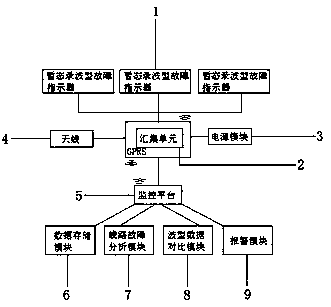
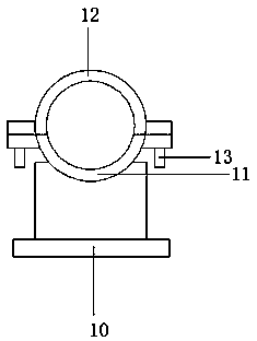
[0015] see Figure 1-2 , the present invention provides a technical solution: comprising a transient recording type fault indicator 1, a collection unit 2, a monitoring platform 5 and a fixing seat 10, the transient recording type fault indicator 1 is connected with a collection unit through wireless communication 2. The collection unit 2 is linearly connected with a power module 3 and an antenna 4, and the collection unit 2 is connected with a monitoring plat...


PUM


Abstract

The invention discloses a line test system and a test tool based on a transient wave recording type fault indicator, comprising the transient wave recording type fault indicator, a collecting unit, amonitoring platform and a fixing seat, wherein the transient wave recording type fault indicator is connected to the collecting unit by wireless communication, the collecting unit is linearly connected with a power module and an antenna, the collecting unit is connected to the monitoring platform by wireless communication, the monitoring platform is linearly connected with a data storage module, aline fault analysis module, a wave mode data comparison module and an alarm module, a lower fixing groove is formed in an upper end of the fixing seat, the lower fixing groove is connected and provided with an upper fixing groove by a bolt button, the line test system and the test tool disclosed by the invention upload data to the monitoring platform through the wireless communication, and monitor the line fault information and operating conditions of a power distribution network, and the test tool can fix and clamp the transient wave recording type fault indicator, so that the transient waverecording type fault indicator can be conveniently detected.

Description

technical field [0001] The invention relates to a line testing system and testing tooling for a transient wave recording type fault indicator, in particular to a line testing system and testing tooling based on a transient state wave recording type fault indicator. Background technique [0002] Most of the medium-voltage distribution networks in my country are ungrounded or grounded through arc suppression coils. The single-phase ground fault accounts for about 80% of the total faults, and the selection of fault lines and fault location are very difficult. For a long time, the on-site practical effect of fault line selection and positioning technology is not satisfactory. Operators are more accustomed to using the original method of manual line pulling to determine fault lines and manual line inspection to determine fault points, resulting in unnecessary short-term power outages on healthy lines, and It consumes a lot of manpower and material resources and prolongs the fault...

Claims


Application Information

Patent Timeline
IPC IPC(8): G01R31/08G01R1/04G01R35/00
CPCG01R1/04G01R31/085G01R35/00
Inventor 辛凯任贵卿刘飞飞李加江王丽
Owner 山东电工豪迈节能科技有限公司
Learn More