
Pipe-in-pipe structure convenient for optical cable laying and replacing and laying method

An optical cable laying and pipe-in-pipe technology, which is applied in the field of pipe-in-pipe structure, can solve the problems of long construction period, large lost labor costs, and the quality of optical fiber communication is easily affected by the outside world, and achieves the effect of improving transmission efficiency and increasing benefits.

Pending Publication Date: 2019-08-27
CHINA INST OF WATER RESOURCES & HYDROPOWER RES +1
View PDF0 Cites 5 Cited by
  • Summary
  • Abstract
  • Description
  • Claims
  • Application Information

AI Technical Summary

Problems solved by technology

[0004] The invention aims at the problems in the prior art that the quality of optical fiber communication is easily affected by external influences and the construction period is long due to the influence of weather and pipeline progress in laying optical cables outside the pipeline, and a large amount of work delay costs are generated. Tube-in-tube structure and method for replacing faulty optical cable

Method used


Image

  • Pipe-in-pipe structure convenient for optical cable laying and replacing and laying method

Examples


Embodiment Construction

[0029] The technical solution of the present invention will be described in detail below in conjunction with the accompanying drawings and specific embodiments.

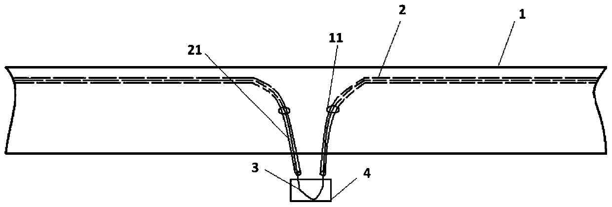
[0030] Such as figure 1 As shown, a pipe-in-pipe structure of the present embodiment that facilitates the replacement of faulty optical cables without pipeline failure includes a transport pipeline 1 and an optical cable channel formed by microtubes 2. The optical cable channel includes several sections, and each section It includes a main body and lead-out sections 21 at both ends. The main body is located on the inner wall of the conveying pipeline 1. The lead-out sections at both ends pass through the lead-out holes 11 on the conveying pipeline 1 and lead out of the conveying pipeline 1. The optical cable 3 is laid on the micro-section of each section. In the optical cable channel formed by the tube, and both ends protrude outside the lead-out section 21, they are fused with the optical fiber in the optical cable ...


PUM

PropertyMeasurementUnit
Outer diameteraaaaaaaaaa
Wall thicknessaaaaaaaaaa
Lengthaaaaaaaaaa

Abstract

The invention discloses a pipe-in-pipe structure convenient for optical cable laying and replacing and a laying method. The structure comprises a conveying pipeline and optical cable channels, whereinthe optical cable channels are divided into a plurality of sections; each section comprises a main body and lead-out sections at both ends; the main bodies are fixed on the inner wall of the conveying pipeline; the lead-out sections at both ends respectively pass through corresponding lead-out holes in the conveying pipeline to be led out of the conveying pipeline; and gaps at the lead-out holesare sealed. During laying, micro tubes are fixed on the inner wall of the conveying pipeline to form the optical cable channels and gaps among the micro tubes are sealed to prevent the micro tubes from gas leaking and water leaking; the micro tubes are led out of the conveying pipeline from the lead-out holes every 1500m to 2500m to form the lead-out sections and gaps between the micro tubes and the lead-out holes are sealed to avoid gas leakage and water leakage; optical cables are laid in the micro-tubes of each section and two ends of the optical cables are exposed out of the micro-tubes; and the optical cables of the adjacent sections are fused together, joints are protected by joint boxes and gaps between the optical cables and the micro tubes are sealed. After the micro tubes are laid, faulty optical cables in the micro tubes can be replaced at the lead-out sections without stopping of the medium conveying in the conveying pipeline.

Description

technical field [0001] The invention relates to a tube-in-tube structure and a laying method that facilitate laying and replacement of optical cables, and is suitable for laying optical cables in pipelines, storage tanks, boilers and other storage and transportation devices and oil wells, and replacing faulty optical cables without stopping or stopping production. Background technique [0002] Pipelines are very important transportation devices. In order to realize the digitalization and intelligence of pipelines, communication optical cables or distributed optical fiber sensors are usually installed along pipelines and other storage and transportation facilities. At present, when the optical cable is laid along the pipeline in the industry, the optical cable is generally laid in the same ditch outside the pipeline, and the optical cable is laid along the axial direction of the pipeline. There are many problems in the installation, laying and failure of the optical cable. ...

Claims


Application Information

Patent Timeline
IPC IPC(8): G02B6/50
CPCG02B6/50
Inventor 朱新民缪宏张霓崔炜周抗冰黄涛缪文韬李海洋杨璐菲
Owner CHINA INST OF WATER RESOURCES & HYDROPOWER RES
Learn More