
Silicon wafer cleaning system

A silicon wafer cleaning and silicon wafer technology, applied in electrical components, semiconductor/solid-state device manufacturing, circuits, etc., can solve the problems of complex docking structure between wafer inserter and cleaning machine

Pending Publication Date: 2019-08-27
阜宁协鑫光伏科技有限公司
View PDF0 Cites 2 Cited by
  • Summary
  • Abstract
  • Description
  • Claims
  • Application Information

AI Technical Summary

Problems solved by technology

Traditionally, the inserting output track of the inserting machine is inconsistent with the feeding mechanism structure of the washing machine, and the docking structure of the inserting machine and the washing machine is complicated

Method used

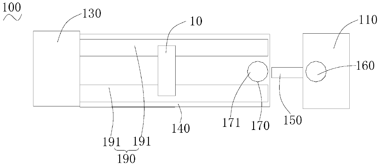
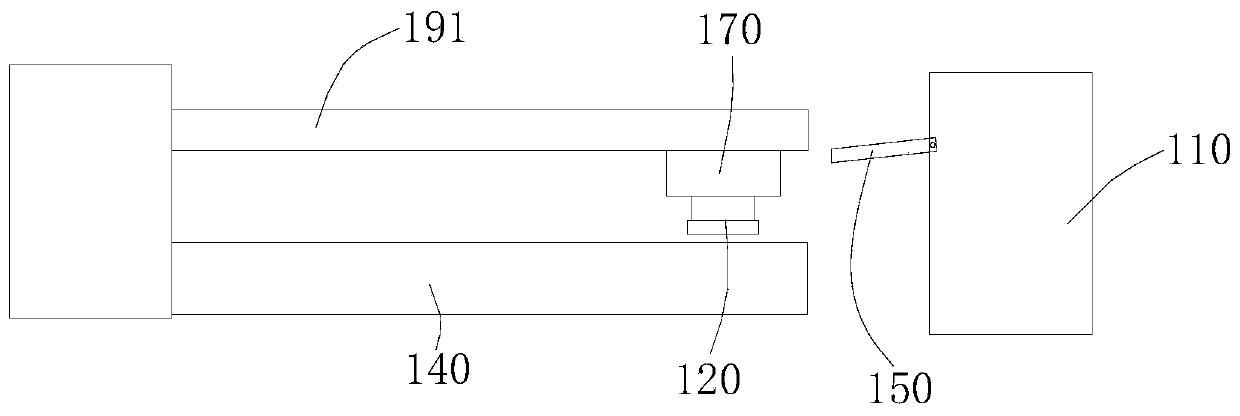

Image

  • Silicon wafer cleaning system
  • Silicon wafer cleaning system

Examples


Embodiment Construction

[0024] In order to make the above objects, features and advantages of the present invention more comprehensible, specific implementations of the present invention will be described in detail below in conjunction with the accompanying drawings. In the following description, numerous specific details are set forth in order to provide a thorough understanding of the present invention. However, the present invention can be implemented in many other ways different from those described here, and those skilled in the art can make similar improvements without departing from the connotation of the present invention, so the present invention is not limited by the specific embodiments disclosed below.

[0025] It should be noted that when an element is referred to as being “fixed” to another element, it can be directly on the other element or there can also be an intervening element. When an element is referred to as being "connected to" another element, it can be directly connected to t...


PUM


Abstract

The invention relates to a silicon wafer cleaning system. The silicon wafer cleaning system comprises a wafer inserting station, a cleaning station, a turnover mechanism, a first rotating mechanism and a conveying rail, wherein the turnover mechanism is used for turning a flower basket loaded with the silicon wafers output by the wafer inserting station to a horizontal state; the first rotating mechanism is used for driving the flower basket which is overturned to the horizontal state to rotate in the horizontal direction at a preset angle; and the conveying rail is used for conveying the flower basket rotated by the first rotating mechanism to the cleaning station. The silicon wafer cleaning system is characterized in that the conveying rail is arranged between the wafer inserting stationand the cleaning station, so that the flower basket loaded with the silicon wafers output by the wafer inserting station is directly conveyed to the cleaning station through the conveying rail afterbeing overturned by the turnover mechanism and rotated by the first rotating mechanism. Only one conveying rail is arranged between the wafer inserting station and the cleaning station, and the problem that the wafer inserting output rail of a traditional wafer inserting machine is not consistent with the feeding structure of a cleaning machine, and the problem that butt joint structure of the wafer inserting machine and the feeding machine is complex can be solved; and in other words, the butt joint mode between the wafer inserting station and the cleaning station is simplified.

Description

technical field [0001] The invention relates to the field of silicon wafer cleaning, in particular to a silicon wafer cleaning system. Background technique [0002] After the silicon wafer is cut, the surface of the silicon wafer has dirt such as silicon debris or cutting fluid, which needs to be cleaned to keep the surface of the silicon wafer clean. Generally, the silicon wafer is cleaned by a silicon wafer cleaning machine. Before cleaning the silicon wafers, the silicon wafers need to be placed in the flower basket through the insertion machine. [0003] Traditionally, inserting machines and washing machines are set up separately. The inserting machine is provided with an inserting output track, and the washing machine is provided with a feeding bracket and a movable feeding mechanism arranged on the feeding bracket. Traditionally, the inserting output track of the inserting machine is inconsistent with the feeding mechanism structure of the washing machine, and the d...

Claims


Application Information

Patent Timeline
IPC IPC(8): H01L21/67H01L21/02
CPCH01L21/67017H01L21/67023H01L21/02041H01L21/02057
Inventor 但汉满
Owner 阜宁协鑫光伏科技有限公司
Learn More