Eureka AIR delivers breakthrough ideas for toughest innovation challenges, trusted by R&D personnel around the world.

Support beam switching device

A technology of switching device and support beam, applied in the field of ropeway, can solve the problems of narrow space of tire beam, inconvenient operation, complicated structure, etc., and achieve the effect of compact structure, simplified structure and small footprint

Pending Publication Date: 2019-11-12
BEIJING MATERIALS HANDLING TECH INST CO LTD
View PDF0 Cites 0 Cited by
  • Summary
  • Abstract
  • Description
  • Claims
  • Application Information

AI Technical Summary

Problems solved by technology

[0006] The purpose of the present invention is to provide a support beam switching device to solve one of the technical problems of inconvenient operation, narrow space and complex structure of the tire beam when switching the cableway path in the prior art or related technology

Method used


Image

  • Support beam switching device
  • Support beam switching device
  • Support beam switching device

Examples


Embodiment Construction

[0041] The specific implementation manners of the present invention will be further described in detail below in conjunction with the accompanying drawings and embodiments. The following examples are used to illustrate the present invention, but are not intended to limit the scope of the present invention.

[0042] In the description of the present invention, it should be noted that the terms "center", "longitudinal", "transverse", "upper", "lower", "front", "rear", "left", "right", " The orientations or positional relationships indicated by "vertical", "horizontal", "top", "bottom", "inner", "outer", etc. are based on the orientation or positional relationships shown in the drawings, and are only for the convenience of describing the present invention and simplifying Describes, but does not indicate or imply that the device or element referred to must have a specific orientation, be constructed in a specific orientation, and operate in a specific orientation, and therefore sh...


PUM


Abstract

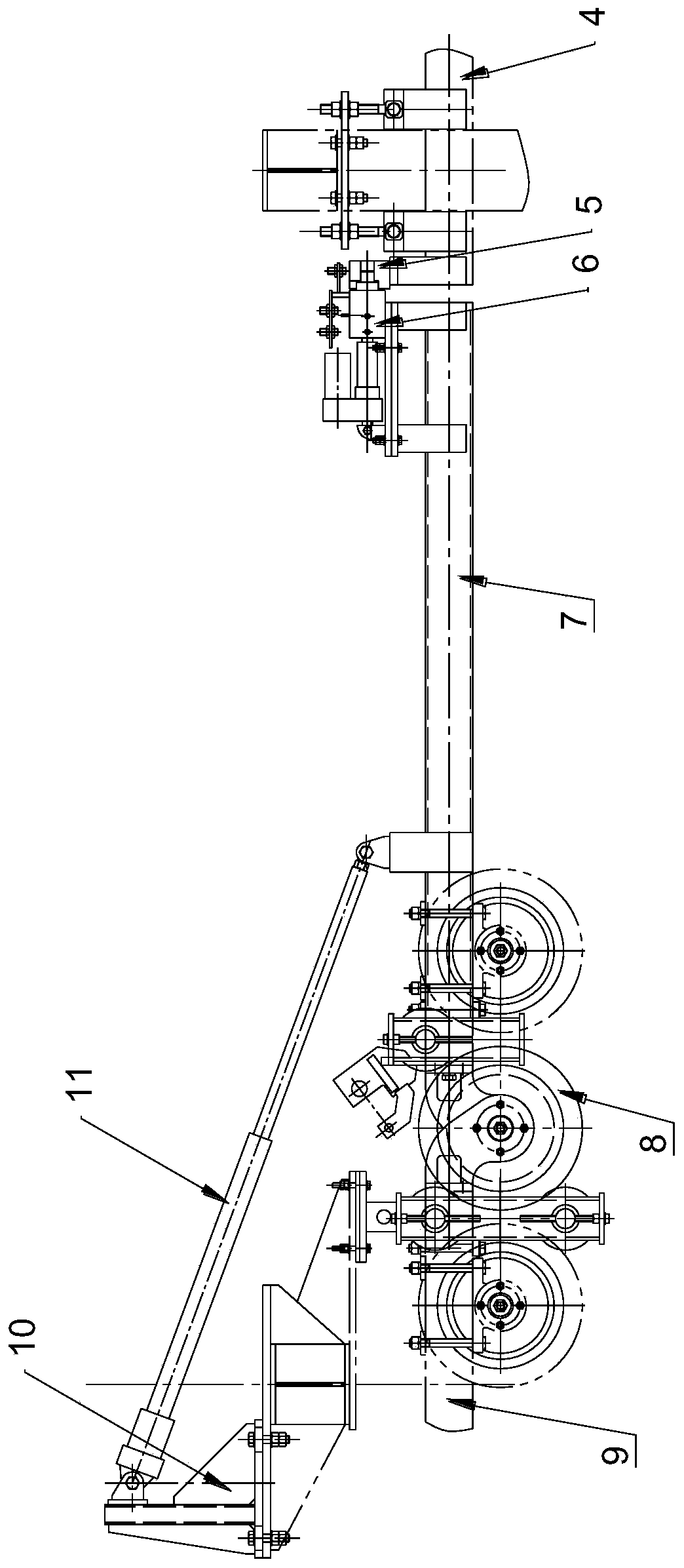
The invention relates to the technical field of cableway, and discloses a support beam switching device. The support beam switching device is used for butt joint between a first support beam and a second support beam or between the first support beam and a third support beam. The support beam switching device comprises a positioning device; the positioning device comprises a pin shaft assembly anda plug pin seat assembly; the first support beam is connected with the pin shaft assembly or the plug pin seat assembly; the second support beam and the third support beam are each provided with thepin seat assembly matched with the pin shaft assembly or the pin shaft assembly matched with the pin seat assembly; the pin shaft assemblies comprise linear driving parts, positioning seats and pin shafts; the output ends of the linear driving parts are connected with the first ends of the pin shafts; the pin shafts penetrate through the positioning seats, and the second ends of the pin shafts canextend out of positioning bosses at the end parts of the positioning seats; the positioning bosses are coaxial with the pin shafts; the plug pin seat assemblies comprise plug pin seats; the plug pinseats comprise positioning grooves matched with the positioning bosses and pin shaft holes matched with the pin shafts; and the positioning grooves are coaxial with the pin shaft holes. The supportingbeam switching device is simple and compact in structure and saves installation space.

Description

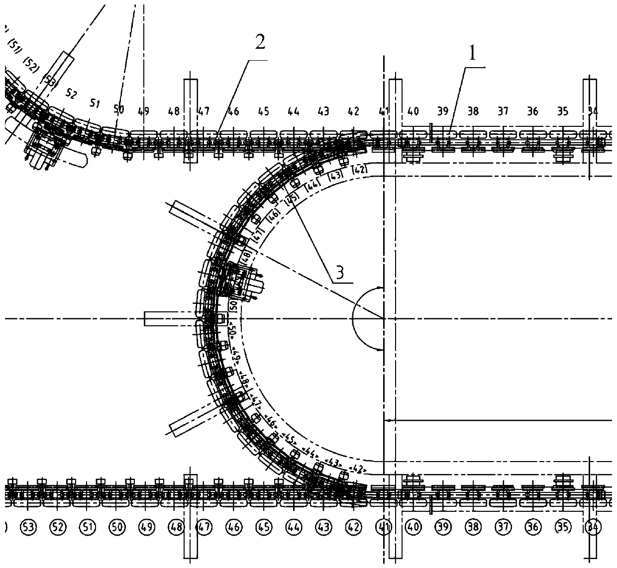
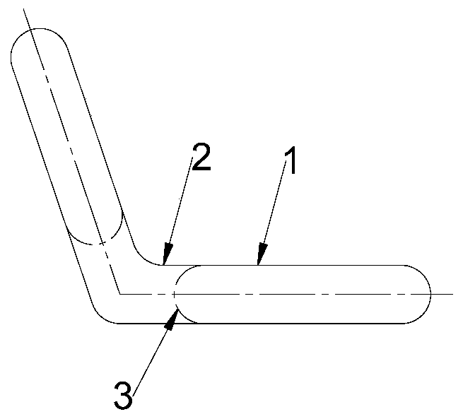
technical field [0001] The invention relates to the technical field of cableways, in particular to a support beam switching device. Background technique [0002] The cableway is a device that uses steel cables suspended in the air to support and pull passenger cars or trucks. Cableways are divided into single-track, double-track, reciprocating, circular, detachable and other forms according to the support and traction methods. The detachable cableway is convenient to get on and off, has a high level of automation, strong ability to adapt to the terrain, is safe and fast, and has a large transportation capacity. It is currently the mainstream equipment type of cableway at home and abroad. [0003] Such as figure 1 and figure 2 As shown, the cableway with an intermediate station includes an acceleration and deceleration section 1, a straight section 2 and a curved section 3. When the traveling path of the cableway is along the direction from the acceleration and decelerati...

Claims


Application Information

Patent Timeline
Patent Type & Authority Applications(China)
IPC IPC(8): B61B12/00
CPCB61B12/00
Inventor 李刚李越秀黄山
Owner BEIJING MATERIALS HANDLING TECH INST CO LTD
Why Eureka
Eureka Blog
Learn More