Projection equipment for realizing full-color DLP through dual-channel LED
A projection equipment, dual-channel technology, applied in the field of dual-channel LED to realize full-color DLP projection equipment, can solve the problems of high cost and power consumption
- Summary
- Abstract
- Description
- Claims
- Application Information
AI Technical Summary
Problems solved by technology
Method used
Image
Examples
Embodiment 1
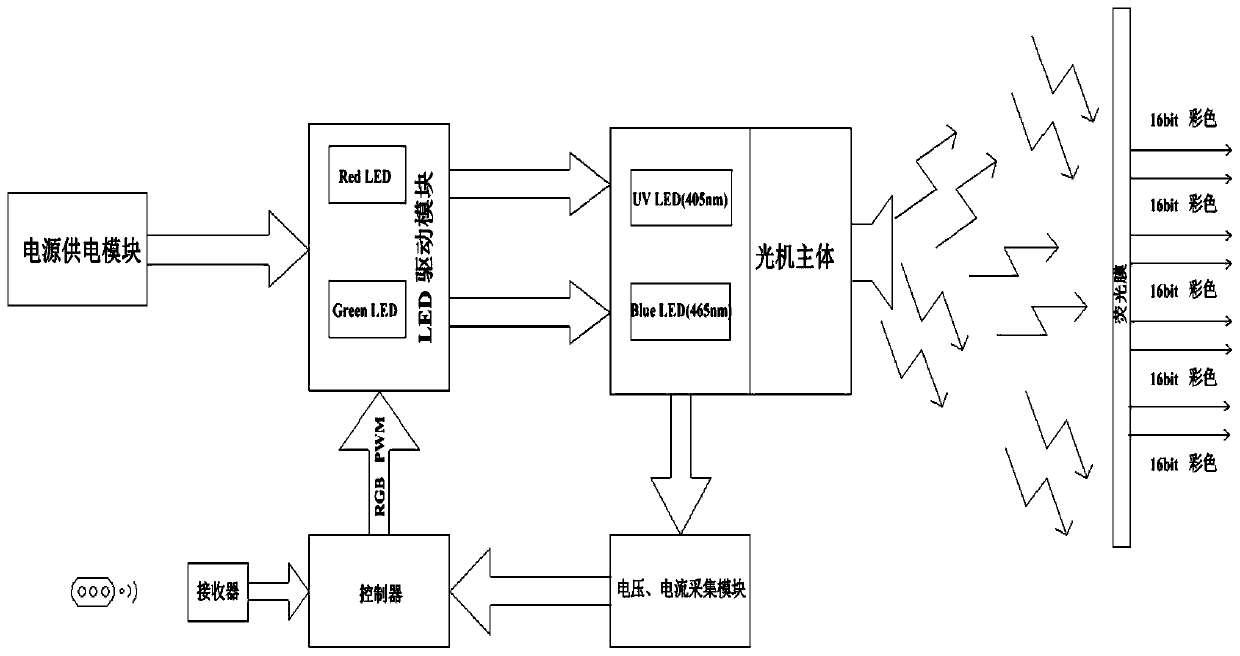
[0042] see figure 1 , the present embodiment provides a dual-channel LED to realize full-color DLP projection equipment, which includes a fluorescent film, an optical machine body, an LED driver module, and a controller, and may also include an acquisition module (i.e., a voltage and current acquisition module) and a receiver .
[0043] The fluorescent film is provided with fluorescent powder, and the fluorescent powder has at least three colors, and the three colors are R, G, and B respectively. In this embodiment, the fluorescent film has a fluorescent layer, and the number of the fluorescent layer is at least one, preferably, the number of the fluorescent layer is two. The fluorescent powder is arranged in the fluorescent layer, and the fluorescent powder can convert external energy into light, and can emit light of various colors. The fluorescent powder in this embodiment is a fluorescent powder excited by a light beam, and it is in the form of a powder. It is a photolumin...
Embodiment 2
[0058] see Figure 4 , this embodiment provides a full-color DLP projection device realized by dual-channel LEDs, which adds a part of the circuit structure on the basis of Embodiment 1. Wherein, the LED driving module also includes MOS transistors Q6 and MOS transistors Q7 each having eight pins, resistors R1, R2, capacitors C2, C3, and diodes D1, D2. Of course, in some embodiments, the foregoing circuit devices may also belong to part of the circuit structure in the main body of the optical machine.
[0059] The same end of the resistors R1 and R2, the negative poles of the diodes D1 and D2, and the positive poles of the UV lamp and LED2 are all connected to the positive output terminal of the power supply module. One end of the capacitor C2 is connected to the other end of the resistor R1, and one end of the capacitor C3 is connected to the other end of the resistor R2. The anode of the diode D4 is connected to one end of the resistor R15, and the cathode is connected to ...
Embodiment 3
[0062] see Figure 5 , this embodiment provides a dual-channel LED to achieve full-color DLP projection equipment, which specifies the circuit structure of the acquisition module (ie, the voltage and current acquisition module) on the basis of Embodiment 2. Wherein, the voltage sampling circuit includes resistors R4, R8 and capacitor C4, and the current sampling circuit includes resistor R15.
[0063] One end of the resistor R4 is connected to the positive output terminal of the power supply module, and the other end is connected to one end of the capacitor C4 and one end of the resistor R8; the other end of the capacitor C4 and the other end of the resistor R8 are both grounded; wherein, the voltage sampling circuit The sampling voltage is:
[0064]
[0065] In the formula, U_led_in is the output voltage of the power supply module.
[0066]The acquisition module also includes a current sampling circuit, and the current sampling circuit includes a resistor R15. Pin 1, pi...
PUM
 Abstract
Description
Claims
Application Information
 - R&D
- Intellectual Property
- Life Sciences
- Materials
- Tech Scout
- Unparalleled Data Quality
- Higher Quality Content
- 60% Fewer Hallucinations
Browse by: Latest US Patents, China's latest patents, Technical Efficacy Thesaurus, Application Domain, Technology Topic, Popular Technical Reports.
© 2025 PatSnap. All rights reserved.Legal|Privacy policy|Modern Slavery Act Transparency Statement|Sitemap|About US| Contact US: help@patsnap.com


