Eureka AIR delivers breakthrough ideas for toughest innovation challenges, trusted by R&D personnel around the world.

Light emitting component and manufacturing method thereof

A technology of optical emission components and lasers, which is applied in the field of communication, can solve problems such as rising operating temperature, affecting the performance of chip optical emission components, and increasing power consumption of optical emission components, so as to maintain good performance, improve stability, and reduce power consumption Effect

Inactive Publication Date: 2019-08-27
APAT OPTOELECTRONICS COMPONENTS
View PDF17 Cites 4 Cited by
  • Summary
  • Abstract
  • Description
  • Claims
  • Application Information

AI Technical Summary

Problems solved by technology

The laser emitting part in the existing 50GPAM4 technology adopts a Transmitter Optical Subassembly (abbreviated as TOSA) formed by packaging an uncooled direct modulation laser (Direct Modulation Laser, abbreviated as DML). The advantage of low cost and easy mass production, however, because the existing laser and chip are set on the cooler, when the light emitting component is working, a large amount of heat generated by the laser will be directly transferred to the chip through the cooler, making the operating temperature of the chip Forced to increase, it also increases the power consumption of the entire light emitting component, which affects the performance of the chip and the entire light emitting component

Method used


Image

  • Light emitting component and manufacturing method thereof
  • Light emitting component and manufacturing method thereof
  • Light emitting component and manufacturing method thereof

Examples


Embodiment Construction

[0034] The following will clearly and completely describe the technical solutions in the embodiments of the present invention with reference to the accompanying drawings in the embodiments of the present invention. Obviously, the described embodiments are only part of the embodiments of the present invention, not all of them. Based on the embodiments of the present invention, all other embodiments obtained by persons of ordinary skill in the art without creative efforts fall within the protection scope of the present invention.

[0035] It should be noted that all directional indications (such as up, down, left, right, front, back...) in the embodiments of the present invention are only used to explain the relationship between the components in a certain posture (as shown in the accompanying drawings). Relative positional relationship, movement conditions, etc., if the specific posture changes, the directional indication will also change accordingly.

[0036] In the present in...


PUM


Abstract

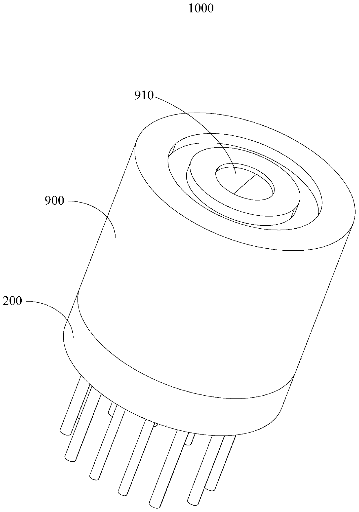
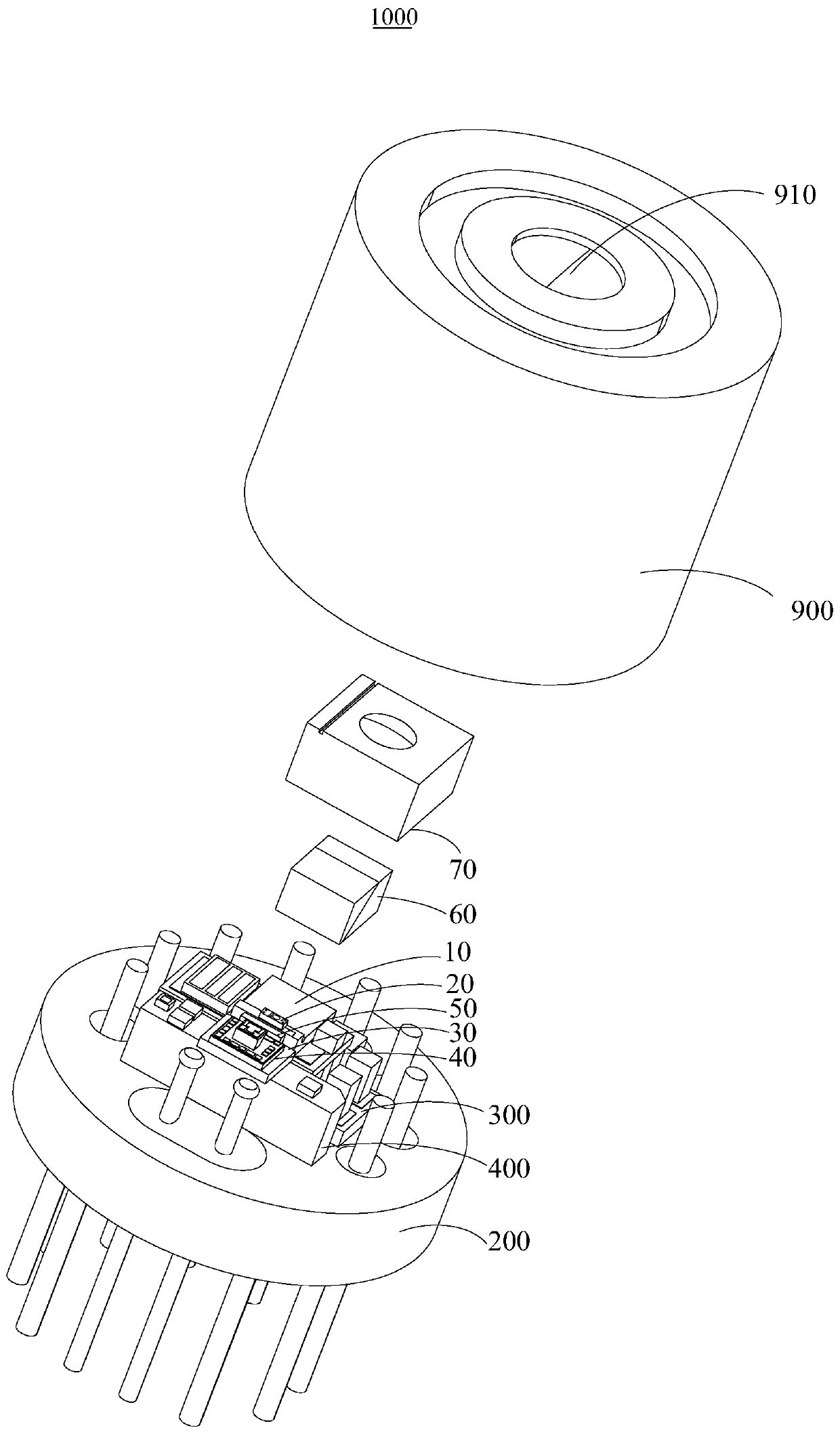
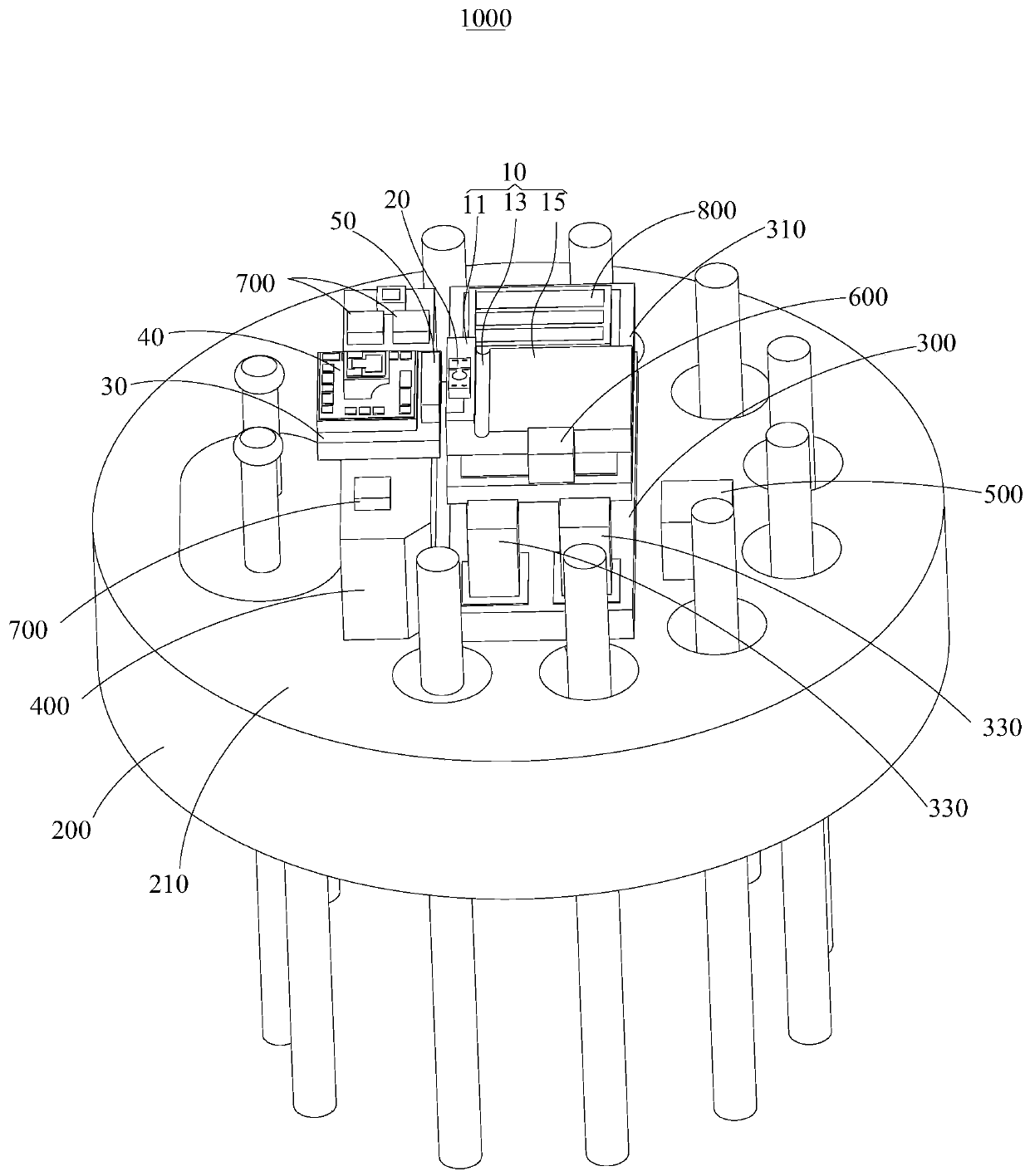
The invention discloses a light emitting component and a manufacturing method thereof. The light emitting component comprises a tube seat; a refrigerator, wherein the refrigerator is disposed on the tube seat; a first conductive block, wherein the first conductive block is disposed on the tube seat and disposed at a distance from the refrigerator; a laser which is disposed on the refrigerator; anda driving chip which is disposed on the first conductive block, and electrically connected with the laser. According to the invention, the influence of the heat generated by the laser on the drivingchip can be reduced, the power consumption of the light emitting component is reduced and the stability of the light emitting component is improved.

Description

technical field [0001] The invention relates to the field of communication technology, in particular to a light emitting component and a manufacturing method of the light emitting component. Background technique [0002] The fifth-generation mobile communication technology (5G) is about to enter commercial use. In order to meet the characteristic requirements of the communication network, most of the current technologies use single-channel 50G PAM4 technology as the optimal solution for adapting to the 5G network. The laser emitting part in the existing 50GPAM4 technology adopts a Transmitter Optical Subassembly (abbreviated as TOSA) formed by packaging an uncooled direct modulation laser (Direct Modulation Laser, abbreviated as DML). The advantage of low cost and easy mass production, however, because the existing laser and chip are set on the cooler, when the light emitting component is working, a large amount of heat generated by the laser will be directly transferred to ...

Claims


Application Information

Patent Timeline
IPC IPC(8): G02B6/42
CPCG02B6/4268G02B6/4271G02B6/4287G02B6/4296
Inventor 庄礼杰苏怡衡杨朝屏万治纬
Owner APAT OPTOELECTRONICS COMPONENTS
Why Eureka
Eureka Blog
Learn More