Liquid-liquid mixer and working method thereof

A mixer and mixing head technology, applied in mixing methods, fluid mixers, chemical instruments and methods, etc., can solve the problems of high resistance, easy blockage, frequent shutdown and maintenance, etc., and achieve the effect of low resistance

Pending Publication Date: 2019-08-30
JIANGSU HENGTAI NATATORIUM EQUIP
View PDF0 Cites 2 Cited by
  • Summary
  • Abstract
  • Description
  • Claims
  • Application Information

AI Technical Summary

Problems solved by technology

For fluids with a lot of suspended solids, this structure has high resistance and is easy to block, requiring frequent shutdowns for

Method used


Image

  • Liquid-liquid mixer and working method thereof
  • Liquid-liquid mixer and working method thereof
  • Liquid-liquid mixer and working method thereof

Examples


Embodiment 1

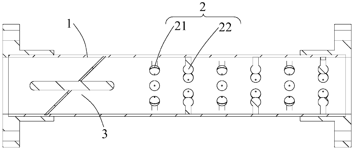
[0057] Such as Figure 1~6 shown

[0058] The invention provides a liquid-liquid mixer, comprising:

[0059] a pipe body 1 and a plurality of mixing units 2 located within said pipe body 1; and

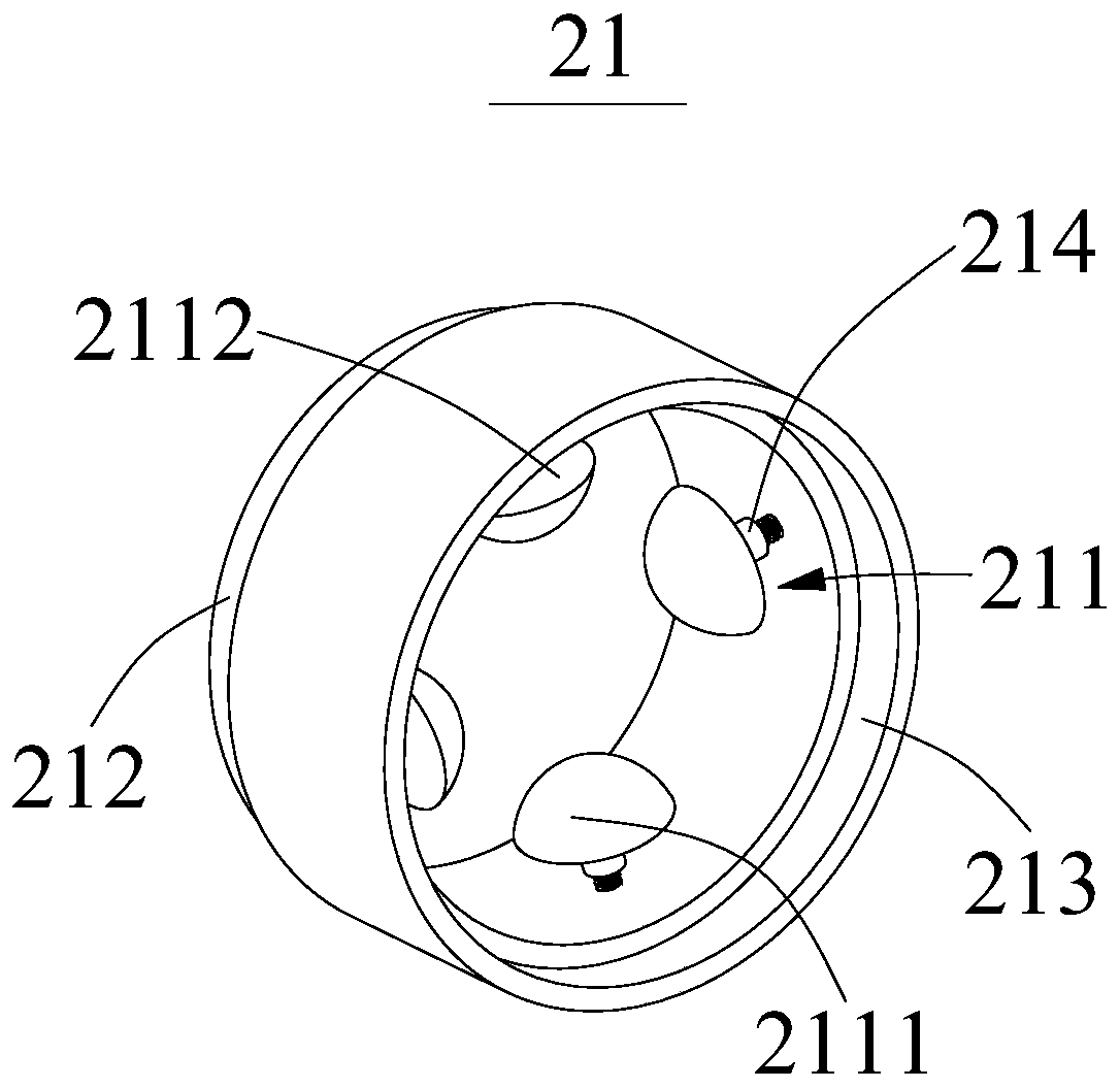
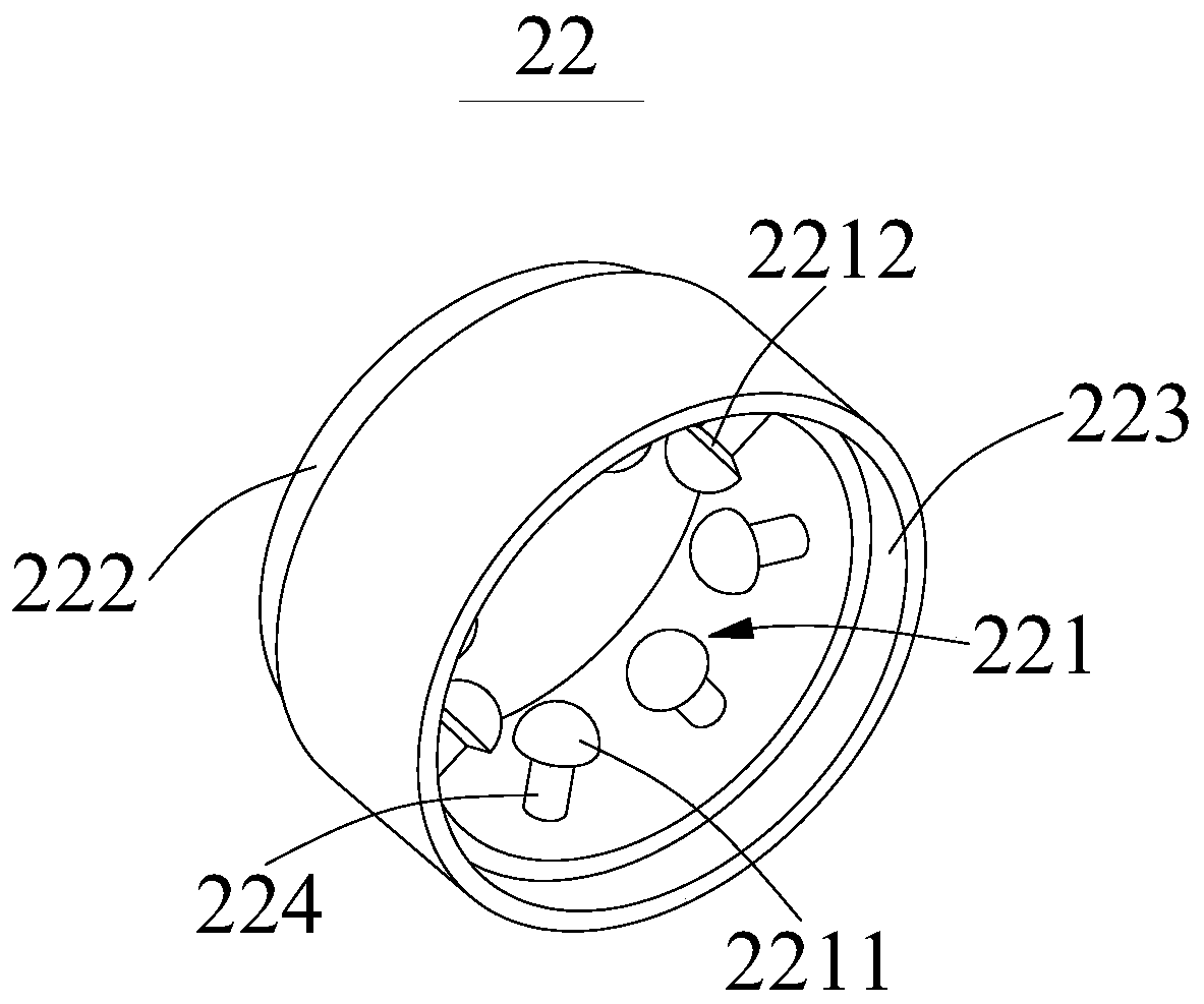
[0060] The mixing unit 2 includes a first mixing part 21 and a second mixing part 22;

[0061] The first mixing part 21 has a plurality of first mixing heads 211, and the second mixing part 22 has a plurality of second mixing heads 221, and each of the first mixing heads 211 is located between two of the second mixing heads. between the axial gaps of the heads 221; the meaning of the axial gap here is the axial gap between the pipeline body 1 and the gap between the two second mixing heads 221, which is the axial gap, and the first mixing head 211 is set At this axial gap, ensure that in each mixing unit 2, the first mixing head 211 and the second mixing head 221 are misplaced. Similarly, in two mixing units 2, the first mixing head 221 in one mixing unit 2 A mixing head 211 is li...

Embodiment 2

[0083] The liquid-liquid mixer of embodiment two is based on the liquid-liquid mixer introduced in embodiment one;

[0084] The working method of this kind of liquid-liquid mixer,

[0085] The liquid-liquid mixer includes a pipeline body 1 and a plurality of mixing units 2 located in the pipeline body 1, the mixing unit 2 includes a first mixing part 21 and a second mixing part 22, and the first mixing part 21 There are a plurality of first mixing heads 211 on the second mixing part 22, and there are several second mixing heads 221 on the second mixing part 22, and each of the first mixing heads 211 is located between two axial gaps of the second mixing heads 221. between;

[0086] The liquid is injected from the liquid inlet of the pipe body 1 , and the dislocation of the first mixing part 21 and the second mixing part 22 disturbs the mixed flow.

[0087] The beneficial effect of the working method of this liquid-liquid mixer is: the form of dislocation disturbing mixed flo...


PUM


Abstract

The invention provides a liquid-liquid mixer and a working method thereof, wherein the liquid-liquid mixer comprises a pipe body and a plurality of mixing units located in the pipe body; and the mixing unit includes a first mixing portion and a second mixing portion; the first mixing portion comprises a plurality of first mixing heads and the second mixing portion comprises a plurality of second mixing heads, each of the first mixing heads is positioned between axial gaps of the two second mixing heads; wherein the liquid can be disturbed by a misalignment between the first mixing head and thesecond mixing head. Through the setting of mixing unit, the effect of mixing liquid guide is realized. Secondly, the preliminary mixing effect is realized by the first mixing head. The effect of secondary mixing is realized by the second mixing head, and the effect of staggered disturbance mixing flow of liquid is realized by staggered setting of the first mixing head and the second mixing head.The dispersed cutting, reverse rotation, radial mixing effect of the liquid is promoted, and low pressure resistance, high efficiency and uniform mixing effect are achieved.

Description

technical field [0001] The invention relates to the field of static mixers, in particular to a liquid-liquid mixer and a working method thereof. Background technique [0002] A static mixer is a stirring and mixing device with no moving parts inside. Its working principle is to use the mixing element fixed in the tube to continuously change the direction and state of the fluid flow, so that the fluids can be cut, rotated, and mixed, so as to achieve a good dispersion and mixing effect between different fluids. Compared with other equipment in terms of mixing, static mixer has the advantages of simple process, low energy consumption, small volume, low investment, convenient operation and easy realization of continuous mixing process, etc. It is an ideal equipment to solve the problem of fully mixing two or more fluids. [0003] Most of the existing static mixers are composed of bent plates or twisted helical sheets. The bent plates or helical sheets intersect each other and ...

Claims


Application Information

Patent Timeline
IPC IPC(8): B01F5/06B01F3/08
CPCB01F23/45B01F25/431B01F25/4317B01F25/431971
Inventor 毛澍洲张波陈征宇胡珊倪晓军殷科峰拾亚男
Owner JIANGSU HENGTAI NATATORIUM EQUIP
Why Eureka
Try Eureka