EGR adjusting device and internal combustion machine

A technology of adjusting device and combustion chamber, applied in charging system, mechanical equipment, engine components, etc., can solve the problems of large intake resistance, large EGR check valve piezoresistance, and high pressure loss

Active Publication Date: 2018-06-12
WEICHAI POWER CO LTD
View PDF6 Cites 2 Cited by
  • Summary
  • Abstract
  • Description
  • Claims
  • Application Information

AI Technical Summary

Problems solved by technology

[0004] As an independent component, the EGR check valve takes up space, which is not conducive to the layout of the whole machine
At the same time, the pressure resistance of the EGR check valve is relatively large, which is not conducive to the improvement of the EGR rate.
When using a mixer to mix EGR exhaust gas and air, the mixing effect of EGR exhaust gas and fresh air is not good, especially the pipeline arrangement with a short mixing distance, it is difficult to ensure the uniformity of mixing
And the structure of the mixer is complex, the pressure loss is high, and the air intake resistance is large

Method used


Image

  • EGR adjusting device and internal combustion machine
  • EGR adjusting device and internal combustion machine
  • EGR adjusting device and internal combustion machine

Examples


Embodiment Construction

[0036] The invention discloses an EGR adjustment device, which optimizes the EGR adjustment structure; the invention also provides an internal combustion engine.

[0037] The technical solutions in the embodiments of the present invention will be clearly and completely described below in conjunction with the accompanying drawings in the embodiments of the present invention. Obviously, the described embodiments are only some, not all, embodiments of the present invention. Based on the embodiments of the present invention, all other embodiments obtained by persons of ordinary skill in the art without making creative efforts fall within the protection scope of the present invention.

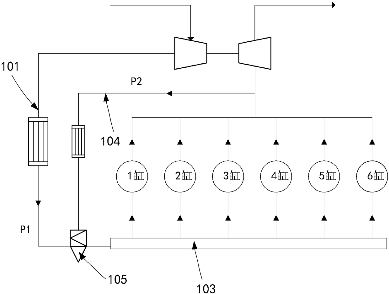
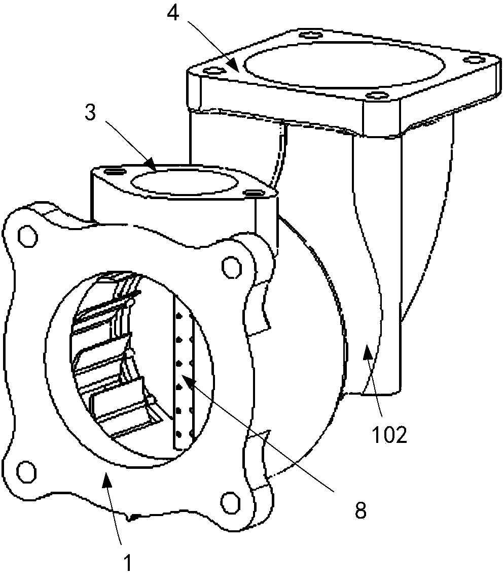
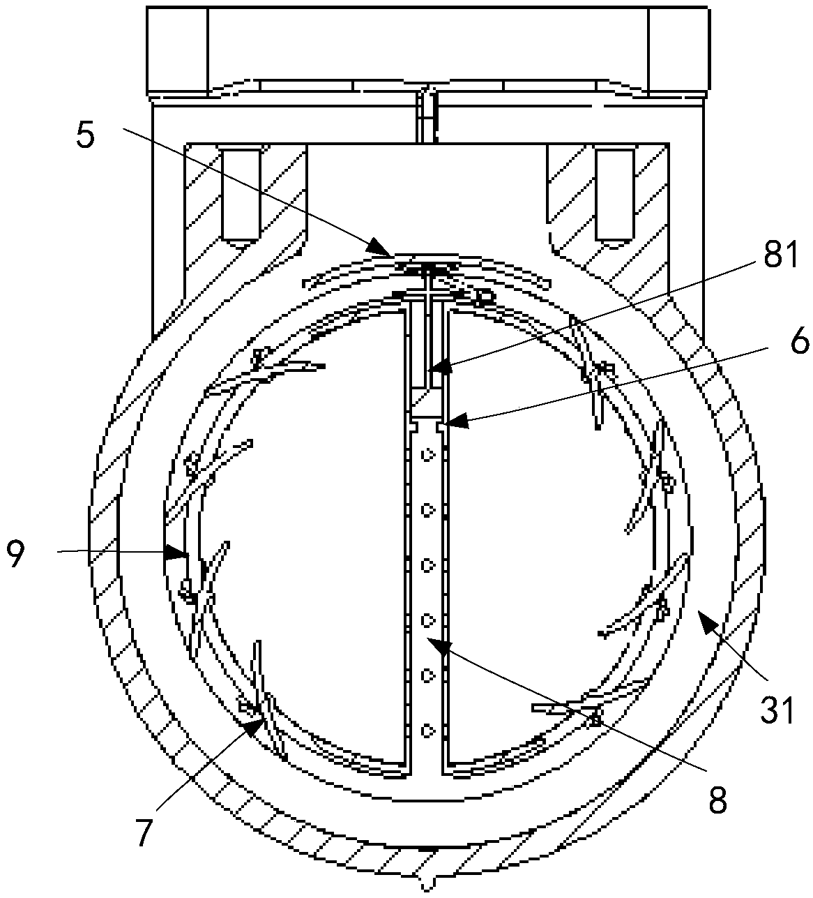
[0038] Such as Figure 1-Figure 5 as shown, figure 1 A schematic diagram of the pipeline connection structure of the EGR regulating device provided by the present invention; figure 2 The front view of the EGR regulating device provided by the present invention; image 3 for figure 2 Cutaway fr...


PUM


Abstract

The invention provides an EGR adjusting device. The device comprises an EGR mixing pipe communicating with an air inlet pipe and a combustion chamber, an EGR mixing cavity is formed in the inlet segment of the air inlet pipe of the EGR mixing pipe, a waste air inlet communicating with the EGR mixing cavity is formed in the side wall of the EGR mixing pipe, a guide pipe arranged in the air inlet direction of the waste air inlet is arranged in the EGR mixing cavity, the guide end of the guide pipe is provided with a guide rod extending out in the air inlet direction of the waste air inlet, the extending-out end of the guide rod is provided with a lifting valve plate for blocking the waste air inlet, the lifting valve plate comprises a first closing side pushed by input air in the air inlet pipe to move upwards and a second opening side pushed by input air of the waste air inlet to move downwards. The waste air inlet is blocked or opened through the lifting valve plate, EGR gas input andbackflow avoiding are achieved, the structure is simplified, the pressure difference between the fresh air and the waste air is used for blocking the waste air inlet, the pressure resistance of the EGR pipeline is small, and the EGR rate is improved. The invention further provides an internal combustion machine.

Description

technical field [0001] The invention relates to the technical field of internal combustion engines, and more specifically relates to an EGR regulating device and an internal combustion engine. Background technique [0002] EGR, Exhaust Gas Recirculation, is the abbreviation of exhaust gas recirculation, that is, a certain amount of exhaust gas is drawn from the exhaust pipe, introduced into the intake pipe to mix with fresh air, and then enters the combustion chamber to participate in combustion, so as to reduce the generation of pollutant NOx in the combustion process Quantitative purpose. [0003] Generally, a one-way valve component is installed separately in the EGR pipeline to prevent the backflow of EGR exhaust gas, and a mixer with a complex structure is used to improve the EGR mixing uniformity. [0004] As an independent component, the EGR check valve takes up space, which is not conducive to the layout of the whole machine. At the same time, the pressure resistan...

Claims


Application Information

Patent Timeline
Patent Type & Authority Applications(China)
IPC IPC(8): F02M26/19
CPCF02M26/19
Inventor 王作峰刘鑫李志杰曾凡
Owner WEICHAI POWER CO LTD
Why Eureka
Try Eureka