
High pressure seal examining device and application method thereof

A sealing and high-pressure technology, which is applied in the direction of earthwork drilling, sealing/packing, and mining fluids, etc., can solve the problems of complex structure, large occupied area, and complex structure of water pipes, and achieve simple structure, low cost, and simplified structure effect

Active Publication Date: 2019-08-30
PUYANG YUANHENG LITONG PETROLEUM MACHINERY
View PDF7 Cites 1 Cited by
  • Summary
  • Abstract
  • Description
  • Claims
  • Application Information

AI Technical Summary

Problems solved by technology

4. During the wellhead pressure test, the maximum pressure, pressure stabilization time or pressure drop must be recorded.
5. When the wellhead pressure test is performed, it must be carried out under the condition that the bolts of the wellhead are fastened intact.
However, in the traditional way, when flushing with multiple rubber cups and cups, multiple water pipes need to be connected, and most of them are controlled separately. Then, the structure of the entire water pipe is relatively complicated, occupying a large area, and the diameter of the wellhead of the oil well is small. , so that it is inconvenient to set up multiple water pipes in the oil well to supply multiple rubber tubes and leather bowls for flushing
In the traditional design, the structure is complex and the cost is high

Method used


Image

  • High pressure seal examining device and application method thereof
  • High pressure seal examining device and application method thereof
  • High pressure seal examining device and application method thereof

Examples


Embodiment Construction

[0036] The following will clearly and completely describe the technical solutions in the embodiments of the present invention with reference to the accompanying drawings in the embodiments of the present invention. Obviously, the described embodiments are only some, not all, embodiments of the present invention. Based on the embodiments of the present invention, all other embodiments obtained by persons of ordinary skill in the art without creative efforts fall within the protection scope of the present invention.

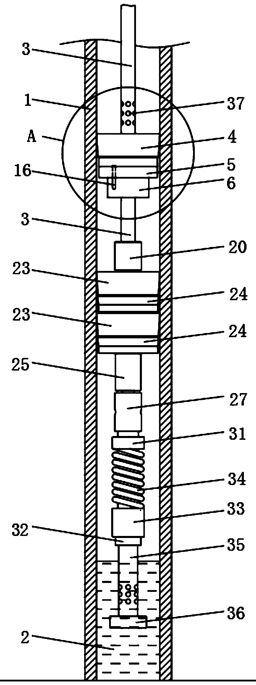
[0037] Such as Figure 1-10 as shown, figure 1 It is a front sectional view of the structure of the present invention;

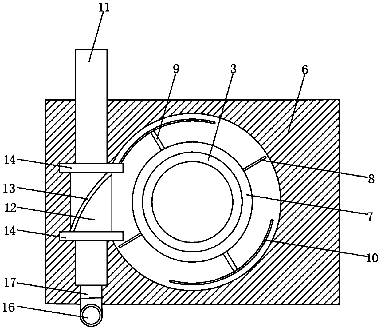
[0038] figure 2 It is a top view of the structure after the section of the fixed block of the present invention;

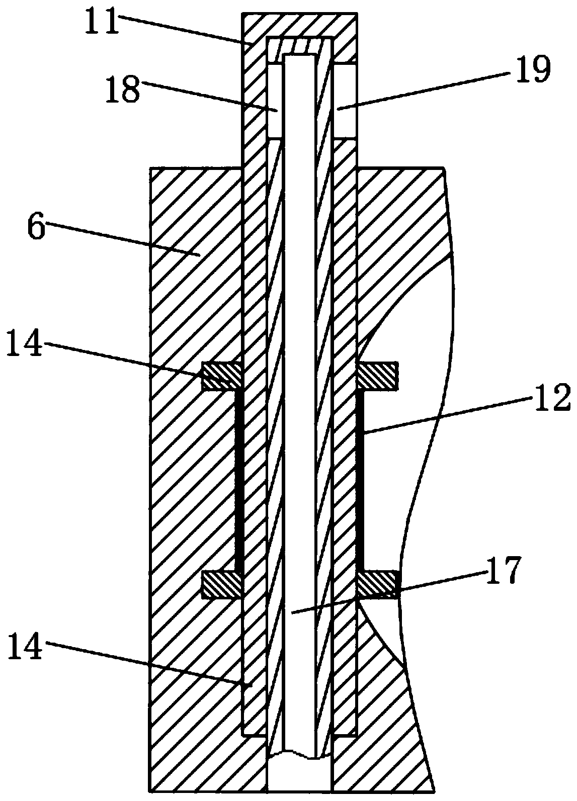
[0039] image 3 It is a top sectional view of the structure of the present invention;

[0040] Figure 4 It is a top view of the sealing flange and connecting pipe structure of the present invention;

[0041] Figure 5 It is...


PUM


Abstract

The invention provides a high pressure seal examining device which comprises an oil suction pipe, a first cup rubber sleeve, a sealing flange plate, a fixed block and a linking sleeve, two transmission columns, two connecting rods, two limiting arc-shaped blocks, an outer sleeve, a transmission pipe and two limiting sleeve blocks. The transmission pipe is provided with two semi-circumferential spiral slots, two limiting slots are formed in the limiting sleeve block, the rotating transmission columns enter the spiral slots to drive the transmission pipe to rotate, the rotating limiting arc-shaped blocks enter into the limiting slot in one limiting sleeve block to rotate and slide out from the limiting slot on the other limiting sleeve block to fix the transmission pipe. The high pressure seal examining device also comprises a connecting pipe and an inner sleeve. The inner sleeve is provided with a first rinsing slot, and the outer sleeve is provided with a second rinsing slot. The highpressure seal examining device also comprises a rubber sleeve supporting rack. A second cup rubber sleeve is fixedly mounted on the rubber sleeve supporting rack. The high pressure seal examining device is simple in structure and relatively low in cost.

Description

technical field [0001] The invention relates to the technical field of high-pressure sealing inspection, in particular to a high-pressure sealing inspection device and a method for using the same. Background technique [0002] Operating procedures for wellhead inspection 1. After running the pressure test string, install the wellhead and fasten all the bolts in the wellhead. 2. Connect the ground pipeline and connect it with the 400-type cement truck, and fasten the joints of the pressure test pipeline. 3. The pipelines of the tanker and the cement truck are connected to ensure no water leakage. 4. Start the cement truck to pressurize, and when the pressure slowly rises to the specified pressure value of the pressure test, stop the cement truck and close the circulation gate. 5. Stabilize the voltage for 15 minutes, and the pressure drop is less than 0.5Mpa, which is qualified. 6. Open the circulation gate of the cement truck to release the pressure, remove the pressure t...

Claims


Application Information

Patent Timeline
IPC IPC(8): E21B33/122E21B47/06E21B43/08E21B21/00
CPCE21B21/00E21B33/122E21B43/086E21B47/06
Inventor 刘喜才范传勇王依明宗珊珊路静李自广
Owner PUYANG YUANHENG LITONG PETROLEUM MACHINERY
Learn More