Anti-pollution fuel tank pressure adjusting device

An adjustment device and anti-pollution technology, which is applied in the direction of oil supply tank device, fluid pressure actuation device, accumulator device, etc., can solve the problem of oil contamination of the oil tank, etc., and achieves easy maintenance, convenient portability, and reduced time costs. Effect

Pending Publication Date: 2019-08-30
NANJING CHENGUANG GRP
View PDF0 Cites 0 Cited by
  • Summary
  • Abstract
  • Description
  • Claims
  • Application Information

AI Technical Summary

Problems solved by technology

[0004] The purpose of the present invention is to provide an anti-pollution fuel tank pressure adjustment device to solve the problem of oil contaminating the fuel tank when the pressure of the pressurized fuel tank is adjusted

Method used


Image

  • Anti-pollution fuel tank pressure adjusting device
  • Anti-pollution fuel tank pressure adjusting device
  • Anti-pollution fuel tank pressure adjusting device

Examples


Embodiment

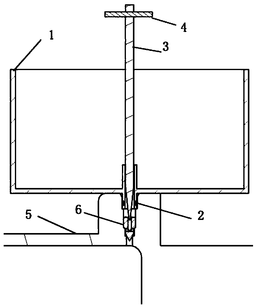
[0019] After the pressurized fuel tank is filled, it is necessary to release air and oil to adjust the pressure of the pressurized fuel tank. The vent hole is set at the highest point of the fuel tank. Contaminate the surface of the fuel tank, especially some sensors, electrical connectors, and valves on the surface of the fuel tank, causing the illusion of oil leakage. In order to solve the problem of air release and oil discharge in the pressurized fuel tank, an anti-pollution fuel tank pressure adjustment device is designed.

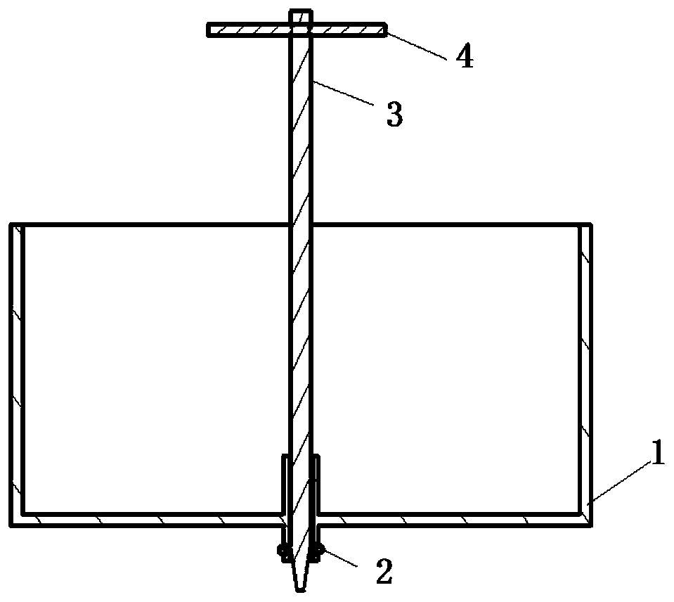
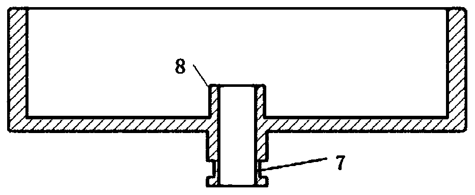
[0020] Such as figure 1 As shown, the oil tank pressure adjustment device includes the oil receiving pan 1, the adjusting rod 3, the force rod 4 and the air release valve 6; the outer circle of the oil receiving pan 1 is designed with a sealing groove 7, and an O-ring is installed on the sealing groove 7 2. The O-ring 2 cooperates with the inner wall of the fuel tank to form a sealing structure to ensure that the air and oil released from the pressur...


PUM


Abstract

The invention discloses an anti-pollution oil tank pressure adjusting device. The device comprises an oil receiving disc, an adjusting rod, a force applying rod and an air discharging valve, wherein the oil receiving disc is arranged above an air discharging hole of a pressurizing oil tank, the bottom of the oil receiving disc extends into the air discharging hole, the adjusting rod extends into the air discharging hole of the pressurizing oil tank through a central hole of the oil receiving disc, the force applying rod is arranged at the top of the adjusting rod, the center hole is higher than the inner bottom face of the oil receiving disc, and the air discharging valve is arranged in the air discharging hole of the pressurizing oil tank. The device is simple in structure, light and convenient to carry, easy to maintain, capable of being repeatedly used and capable of meeting the requirement of pressure regulation of the pressurizing oil tank.

Description

technical field [0001] The invention relates to a pressurized fuel tank pressure regulating technology, in particular to an anti-pollution fuel tank pressure regulating device. Background technique [0002] After the pressurized fuel tank is filled, it is necessary to release air and oil to adjust the pressure of the pressurized fuel tank. The vent hole is set at the highest point of the fuel tank. Contaminate the surface of the fuel tank, especially some sensors, electrical connectors, and valves on the surface of the fuel tank, causing the illusion of oil leakage. [0003] At present, the main pressure regulation method of the pressurized fuel tank is to adjust the pressure of the fuel tank by discharging oil and air through the vent hole arranged at the highest point of the pressurized fuel tank. When draining oil, rotate the air release valve with a screwdriver, and the air and oil will overflow along the opening of the valve. The overflowing oil will easily pollute the...

Claims


Application Information

Patent Timeline
Patent Type & Authority Applications(China)
IPC IPC(8): F15B1/26F16J12/00
CPCF15B1/265F16J12/00
Inventor 郭小强王思成曹翀李宁华潇苏太磊袁琪赵晨
Owner NANJING CHENGUANG GRP
Why Eureka
Try Eureka