Dynamic testing equipment and method for blade angle measuring sensor

A technology for measuring sensors and dynamic testing, which is applied to measuring devices, instruments, and electrical devices, etc., and can solve the problem that the blade angle measuring sensor cannot perform performance testing.

Active Publication Date: 2019-08-30
CHINA HANGFA SOUTH IND CO LTD
View PDF6 Cites 5 Cited by
  • Summary
  • Abstract
  • Description
  • Claims
  • Application Information

AI Technical Summary

Problems solved by technology

[0004] The invention provides a dynamic testing device and method for a blade angle measuring sensor to solve the problem that the blade angle measuring sensor cannot be tested according to the actual installed state

Method used


Image

  • Dynamic testing equipment and method for blade angle measuring sensor
  • Dynamic testing equipment and method for blade angle measuring sensor
  • Dynamic testing equipment and method for blade angle measuring sensor

Examples


Embodiment Construction

[0026] It should be noted that, in the case of no conflict, the embodiments in the present application and the features in the embodiments can be combined with each other. The present invention will be described in detail below with reference to the accompanying drawings and examples.

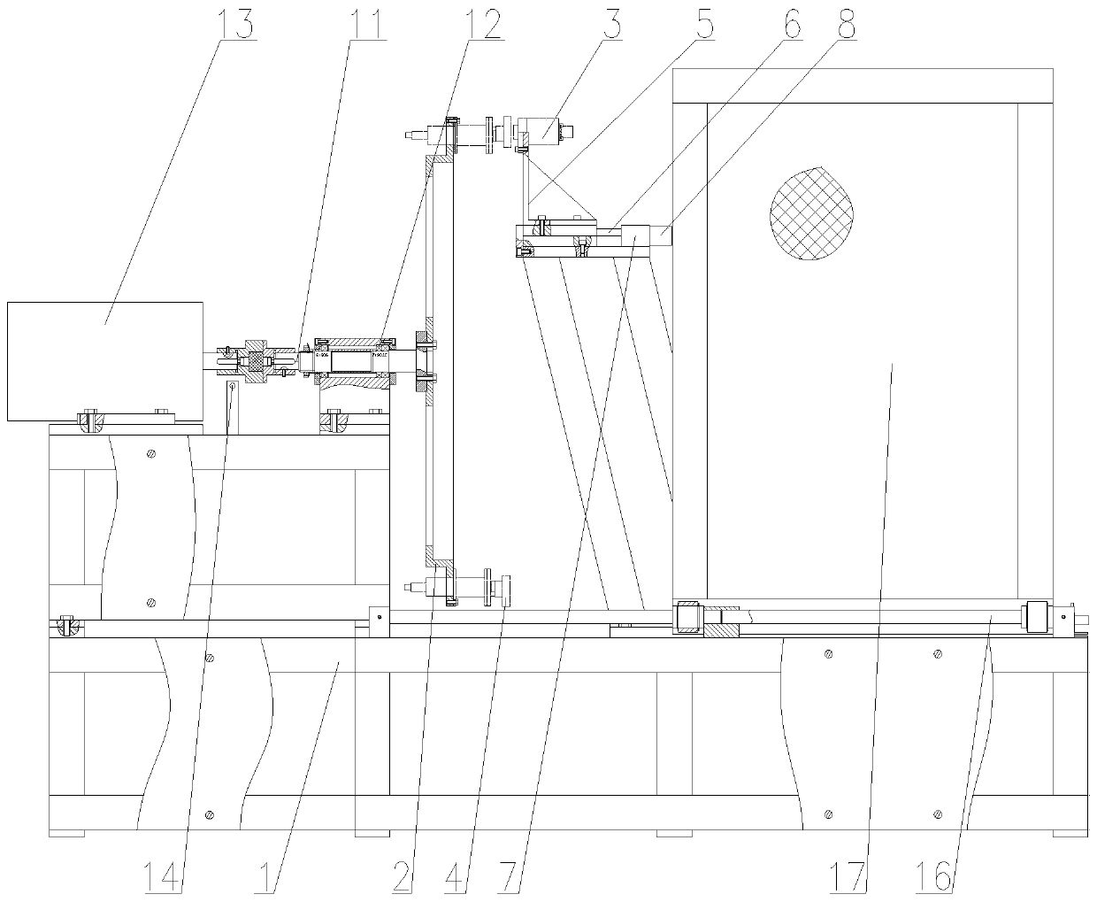
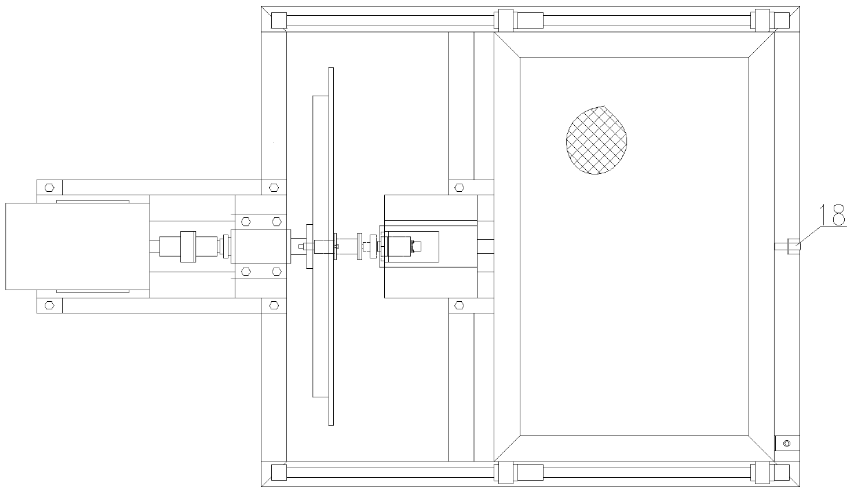
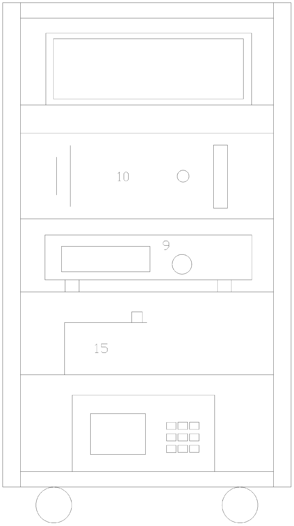
[0027] figure 1 It is one of the schematic diagrams of the dynamic test equipment for the blade angle measurement sensor in the preferred embodiment of the present invention; figure 2 It is the second schematic diagram of the dynamic test equipment for the blade angle measurement sensor in the preferred embodiment of the present invention; image 3 It is the third schematic diagram of the dynamic test equipment for the blade angle measurement sensor in the preferred embodiment of the present invention; Figure 4 It is a schematic flow chart of distance closed-loop control in a preferred embodiment of the present invention.

[0028] like figure 1 , figure 2 and image 3 As shown, the dyn...


PUM


Abstract

The invention provides dynamic testing equipment and method for a blade angle measuring sensor. The dynamic testing equipment of the blade angle measuring sensor comprises a base, a rotating disc which is rotationally connected to the base and is used for simulating a propeller hub of a propeller, a driving mechanism arranged on the base and used for driving the rotating disc to rotate, a positioning mechanism arranged on the base and used for mounting the blade angle measuring sensor, driving the blade angle measuring sensor to move in the axial direction of the rotating disc and feeding backa moving distance, an induction disc arranged on the rotating disc and used for being matched with the blade angle measuring sensor for measurement, and a control mechanism used for collecting the moving distance fed back by the positioning mechanism and a voltage value output by the blade angle measuring sensor and acquiring the linearity of the blade angle measuring sensor. The control mechanism is used for carrying out multi-point collection on the moving distance of the blade angle measuring sensor fed back by the positioning mechanism and the voltage value output by the blade angle measuring sensor, and calculating the linearity of the blade angle measuring sensor by taking the moving distance as an input and taking the voltage value as an output.

Description

technical field [0001] The invention relates to the technical field of aero-engine sensor testing, in particular to a dynamic testing device for a blade angle measurement sensor. In addition, the present invention also relates to a dynamic testing method for the blade angle measuring sensor using the dynamic testing equipment for the blade angle measuring sensor. Background technique [0002] With the improvement of engine performance, it is necessary to use the blade angle measurement sensor to accurately measure the change of the blade angle, so as to realize the closed-loop control of the engine speed. For the measurement principle of the blade angle measurement sensor, refer to patent 201510815877.0: the blade angle measurement device mainly includes a cam, a push rod, and a blade angle measurement sensor. When the paddle shaft rotates to change the blade angle, the cam installed on the paddle shaft rotates with the paddle shaft, pushing the ejector rod to move linearly...

Claims


Application Information

Patent Timeline
Patent Type & Authority Applications(China)
IPC IPC(8): G01B7/30
CPCG01B7/30G01B21/042
Inventor 沈奔姚成林彭景李洪武杨敬宇吴笃华王双刘敏张艳玲
Owner CHINA HANGFA SOUTH IND CO LTD
Why Eureka
Try Eureka