Cascade bent tail plate with hole groove structure for suction type transonic velocity plane cascade turbine test bed

A transonic and tailgate technology, which is applied in the direction of gas turbine engine testing, machine/structural component testing, mechanical component testing, etc., can solve problems such as no obvious improvement, over-expansion, and increased demand for turbine test benches, and achieve easy The effect of simple implementation and structure

Active Publication Date: 2019-08-30
NANJING UNIV OF AERONAUTICS & ASTRONAUTICS
View PDF11 Cites 13 Cited by
  • Summary
  • Abstract
  • Description
  • Claims
  • Application Information

AI Technical Summary

Problems solved by technology

[0002] The planar cascade turbine test bench is an important device for measuring the aerodynamic performance and film cooling performance of turbine blades. With the development of engine technology, the demand for a turbine test bench with a wide Mach number range and a wide range of attack angles is increasing. At the same time The suction-type transonic planar cascade turbine test rig with high safety and reliability is favored by everyone, but this type of test rig usually has straight When the wake of the blade cascade of the test bench of the tail plate turns from the straight tail plate to the outlet pipe, over-expansion will occur due to the large pressure difference
In this regard, the existing tests usually adopt the scheme of not having a tail plate or opening a hole in a straight tail plate, but none of them have significantly improved this phenomenon

Method used


Image

  • Cascade bent tail plate with hole groove structure for suction type transonic velocity plane cascade turbine test bed
  • Cascade bent tail plate with hole groove structure for suction type transonic velocity plane cascade turbine test bed
  • Cascade bent tail plate with hole groove structure for suction type transonic velocity plane cascade turbine test bed

Examples


Embodiment

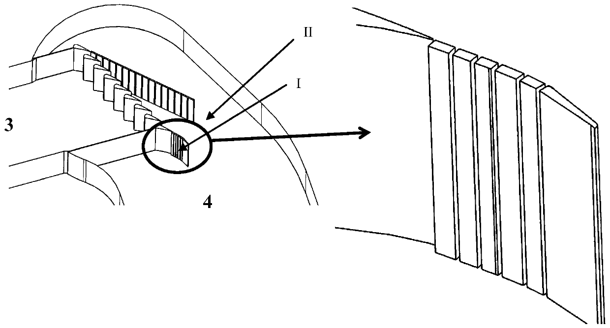
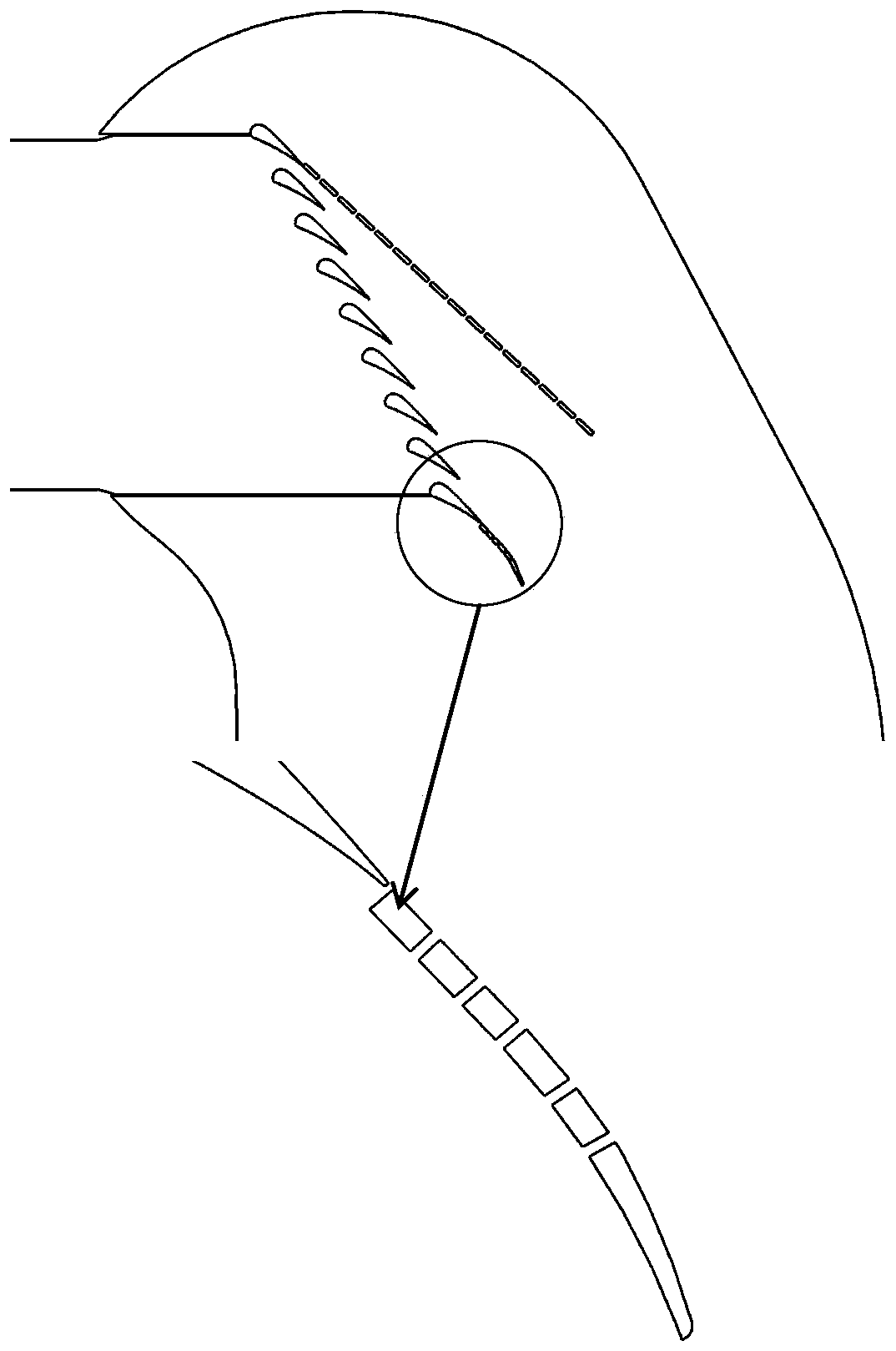
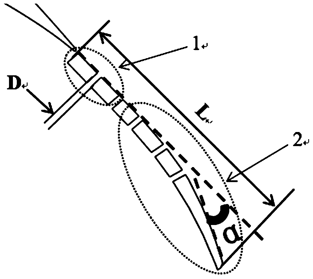
[0025] The invention discloses a suction-type transonic plane blade cascade turbine test stand with a hole-slot structure, and a blade cascade curved tail plate. figure 1 It is a partial three-dimensional schematic diagram of the test section of the suction turbine cascade test bench and the curved tail plate. figure 2 The two-dimensional plan view of the test section of the suction turbine cascade test bench and the curved tail plate, image 3 It is a schematic diagram of the two-dimensional structure of the curved tail plate, Figure 4 It is a schematic diagram of the comparison of the wake pressure contour line between the curved tailgate and the traditional straight tailgate under the conditions of Ma2.0 and -25° attack angle.

[0026] The curved tail plate with a hole-slot structure for improving the wake flow field of the cascade wake of the suction-type transonic plane cascade test bench is composed of an inner curved tail plate and a hole-shaped or groove-shaped holl...


PUM


Abstract

The invention provides a cascade bent tail plate with a hole groove structure for a suction type transonic velocity plane cascade turbine test bed, which is used for improving a cascade wake flow field of the suction type transonic velocity plane cascade turbine test bed. The tail plate is mainly composed of an inner side curved type tail plate and a hole-shaped or groove-shaped hollow structure on the tail plate, wherein the inner side curved type tail plate comprises two-part geometric structures including a straight segment and a quadratic curve segment, and the tail plate is provided withthe hole-shaped or groove-shaped hollow structure. Under a working condition of a high Mach number large negative attack angle test, usage of a curved shape surface of the tail plate and the hole-shaped or groove-shaped hollow structure on the tail plate can prevent a wake from being over-expanded when the wake disengaging the tail plate to enter a suction channel. The two structures make the pressure of the wake rise to the suction pipeline pressure approaching an outlet at an end section of the tail plate, the over-expansion phenomenon is avoided when the tail plate is disengaged, thereby avoiding damage of turbine plane blade cascade periodicity, and at the same time, it finds through calculation that usage of the bent tail plate have no deterioration in working conditions at differentattack angles of other Mach numbers.

Description

technical field [0001] The invention belongs to the technical field of aero-engine turbine aerodynamic performance measurement systems, and relates to a suction type transonic plane blade cascade test bench, in particular to a suction type transonic plane blade cascade turbine test bench blade cascade with a slot structure Bend the tailgate. Background technique [0002] The plane cascade turbine test bench is an important device for measuring the aerodynamic performance and film cooling performance of turbine blades. With the development of engine technology, the demand for turbine test benches with a wide range of Mach numbers and a wide range of attack angles is increasing. The suction-type transonic plane cascade turbine test bench with high safety and reliability is favored by everyone, but this type of test bench generally has a direct When the wake of the cascade of the test rig of the stern flap is turned from the straight stern flap to the outlet pipe, over-expansi...

Claims


Application Information

Patent Timeline
Patent Type & Authority Applications(China)
IPC IPC(8): G01M15/14G01M13/00
CPCG01M13/00G01M15/14
Inventor 杨荣菲王浩王国良葛宁
Owner NANJING UNIV OF AERONAUTICS & ASTRONAUTICS
Why Eureka
Try Eureka