Head gimbal assembly and magnetic disk device with same
A technology of a magnetic disk device and a gimbal, which is applied to the installation/connection of the transducer head relative to the arm member, the configuration/installation of the recording head, and the alignment of the head frame, which can solve problems such as the bad influence of the magnetic head or the magnetic disk.
- Summary
- Abstract
- Description
- Claims
- Application Information
AI Technical Summary
Problems solved by technology
Method used
Image

Examples
no. 1 Embodiment approach
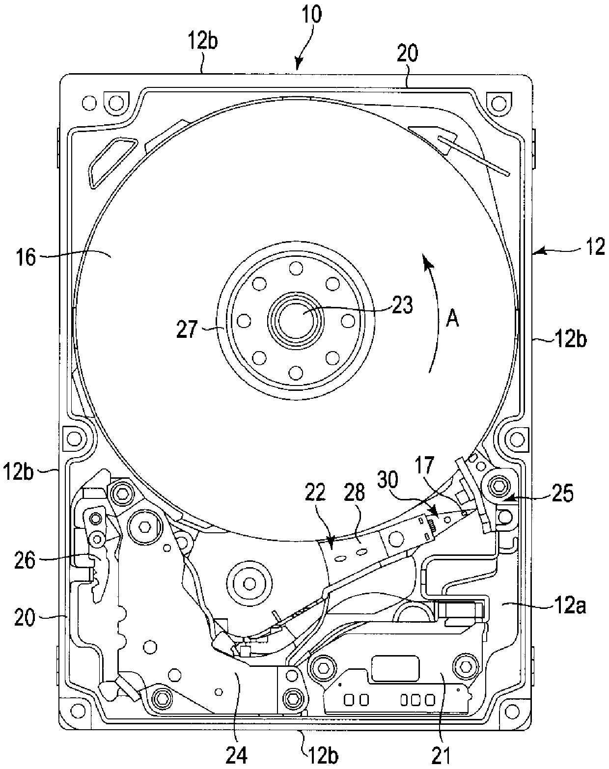
[0025] As an example of a magnetic disk device, a hard disk drive (HDD) according to the embodiment will be described in detail. figure 1 The internal structure of the HDD according to the first embodiment is shown.
[0026] Such as figure 1 As shown, the HDD includes a housing 10 . The frame body 10 has a rectangular box-shaped base 12 with an open top surface, and a top cover (not shown) that closes the upper end opening of the base 12 . The base body 12 has a rectangular bottom wall 12 a and side walls 12 b erected along the periphery of the bottom wall 12 a.
[0027] Inside the casing 10 are provided: one or more magnetic disks 16 as recording media; and a spindle motor 23 as a drive unit that supports and rotates the magnetic disks 16 . The magnetic disk 16 is coaxially fitted to a hub (not shown) of the spindle motor 23 , clamped by a clamp spring 27 , and fixed to the hub. The magnetic disk 16 is rotated at a predetermined speed in the direction of arrow A by the sp...
no. 2 Embodiment approach
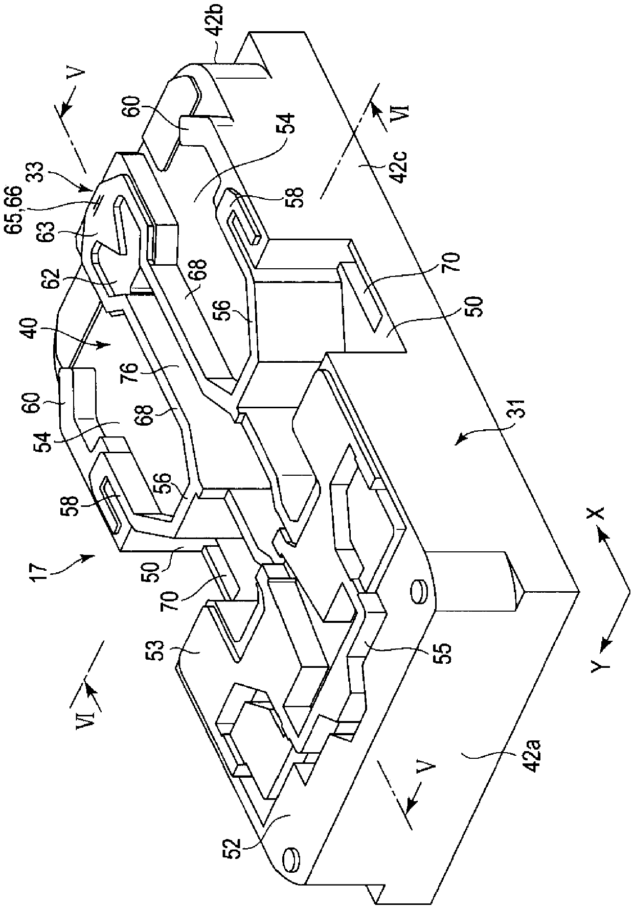
[0056] Figure 8 It is a plan view showing the ABS side of the magnetic head of the HDD according to the second embodiment.
[0057] Such as Figure 8 As shown, according to the second embodiment, the catch groove 70 provided on the bottom surface of the negative pressure generating groove 50 of the slider 31 extends over the entire width of the negative pressure generating groove 50 . That is, the pair of catch grooves 70 are provided in the vicinity of both side surfaces 42 c of the slider 31 . Each catch groove 70 extends in the first direction X from an outflow side step portion (here, a side step 58 ) on the downstream side with respect to the air flow B to the inflow side step portions 52 and 53 . In one example, the capture groove 70 is formed in an elongated rectangular shape or strip shape with a certain width. Each catch groove 70 is arranged adjacent to the side surface 42c with a slight gap therebetween. The width of the catch groove 70 is formed narrower than ...
no. 3 Embodiment approach
[0061] Figure 9 It is a plan view showing the ABS side of the magnetic head of the HDD according to the third embodiment.
[0062] Such as Figure 9 As shown, according to the third embodiment, a plurality of catch grooves 70 are provided on both sides of the bottom surface of the negative pressure generating groove 50 of the slider 31 . In one example, two pairs of capture grooves 70a and 70b are provided on each side. Two catch grooves 70 a and 70 b are provided adjacent to the side surface 42 c of the slider 31 on each side surface 42 c side. The two capture grooves 70a and 70b are arranged in parallel with each other at intervals. Each catch groove 70a, 70b extends in the first direction X from an outflow-side step portion (here, a side step 58 ) on the downstream side with respect to the air flow B to the inflow-side step portion 52 , 53 . The catch grooves 70a and 70b are formed in an elongated rectangular shape or strip shape each having a constant width. Of the t...
PUM
 Abstract
Description
Claims
Application Information
 - R&D
- Intellectual Property
- Life Sciences
- Materials
- Tech Scout
- Unparalleled Data Quality
- Higher Quality Content
- 60% Fewer Hallucinations
Browse by: Latest US Patents, China's latest patents, Technical Efficacy Thesaurus, Application Domain, Technology Topic, Popular Technical Reports.
© 2025 PatSnap. All rights reserved.Legal|Privacy policy|Modern Slavery Act Transparency Statement|Sitemap|About US| Contact US: help@patsnap.com