

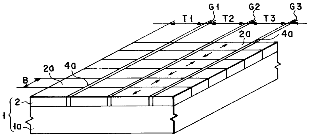
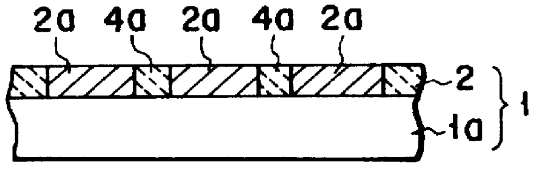
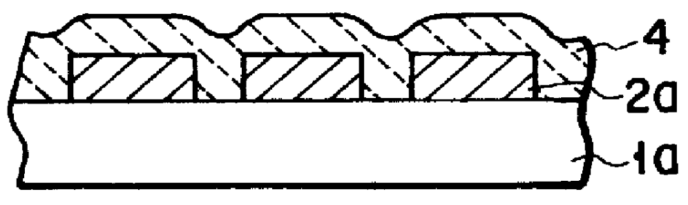
Magnetic disk with a guard band arrangement
a guard band and magnetic disk technology, applied in the field of magnetic disks, can solve the problems of hindering the narrowing of a track, affecting the fringe of the recording magnetic domain, and limited tracking accuracy to mechanical accuracy of the head
- Summary
- Abstract
- Description
- Claims
- Application Information
AI Technical Summary
Problems solved by technology
Method used
Image

Examples
Embodiment Construction
The results of the experiments which clarified the effects of the present invention were described above, but as a comparative example, a magnetic disk without a magnet member was manufactured by the conventional method, and this disk was evaluated similarly to the disk 1D of the above embodiment. The arrangement of the comparative disk is so that a CoPt recording layer of 20 nm and an SiO.sub.2 protective layer of 10 nm were formed on a glass substrate by the sputtering method, and the lubricant which is the same one used for the disk 1D was applied thereto. The conditions of the disk operation test were the same as the disk 1D except that the head fly amount was 0.03 .mu.m and the spacing between the head and media was changed.
A magnetic field which leaks out of the comparative disk to the magnetization rotating film 41 of the head is random in the non-recording state, so the magnetization direction of the magnetization rotating film 41 is arranged in the direction of the leakage ...
PUM
 Abstract
Description
Claims
Application Information