Pulp mixing device

A technology of slurry mixing and slurry tank, which is applied in the direction of mixer with rotating stirring device, transportation and packaging, mixer accessories, etc., which can solve the problems of reducing the use effect, insufficient heating temperature, and low slurry efficiency, so as to improve the use effect , improve the service life, and solve the effect of poor pipeline

Pending Publication Date: 2019-09-03
ZHEJIANG CANAAN TECH
View PDF0 Cites 5 Cited by
  • Summary
  • Abstract
  • Description
  • Claims
  • Application Information

AI Technical Summary

Problems solved by technology

[0002] At present, in the production of pharmaceuticals and food, it is usually necessary to mix and mix powders. When mixing and mixing powders with a large consistency, the existing mixing tanks are in the process of gelatinization and maturation, and the stirring efficiency is not high, resulting in edge positions. Coking occurs in the slurry, and the existing mixing tank is usually heated by a water bath, and the heating temperature is insufficient. In the process of mixing a large volume of powder slurry, it cannot be fully heated, making the slurrying efficiency low, and it is not suitable for Large-volume slurry processing, at the same time, it is difficult to check the position of the heating fluid in the existing slurry mixing tank, and it is difficult to replenish it in time, or add it in place, reducing the use effect
After the slurry mixing is completed, the slurry after the slurry mixing is completed is added to the slurry adding tank, and then transported and cooled through the slurry adding tank, and finally the slurry in the slurry adding tank needs to be discharged for subsequent processing and utilization. The high-consistency slurry is easy to adhere to the side wall of the tank and is difficult to drain, resulting in waste of resources, and the existing slurry discharge structure is inefficient and reduces the use effect of the equipment

Method used


Image

  • Pulp mixing device
  • Pulp mixing device
  • Pulp mixing device

Examples


Embodiment Construction

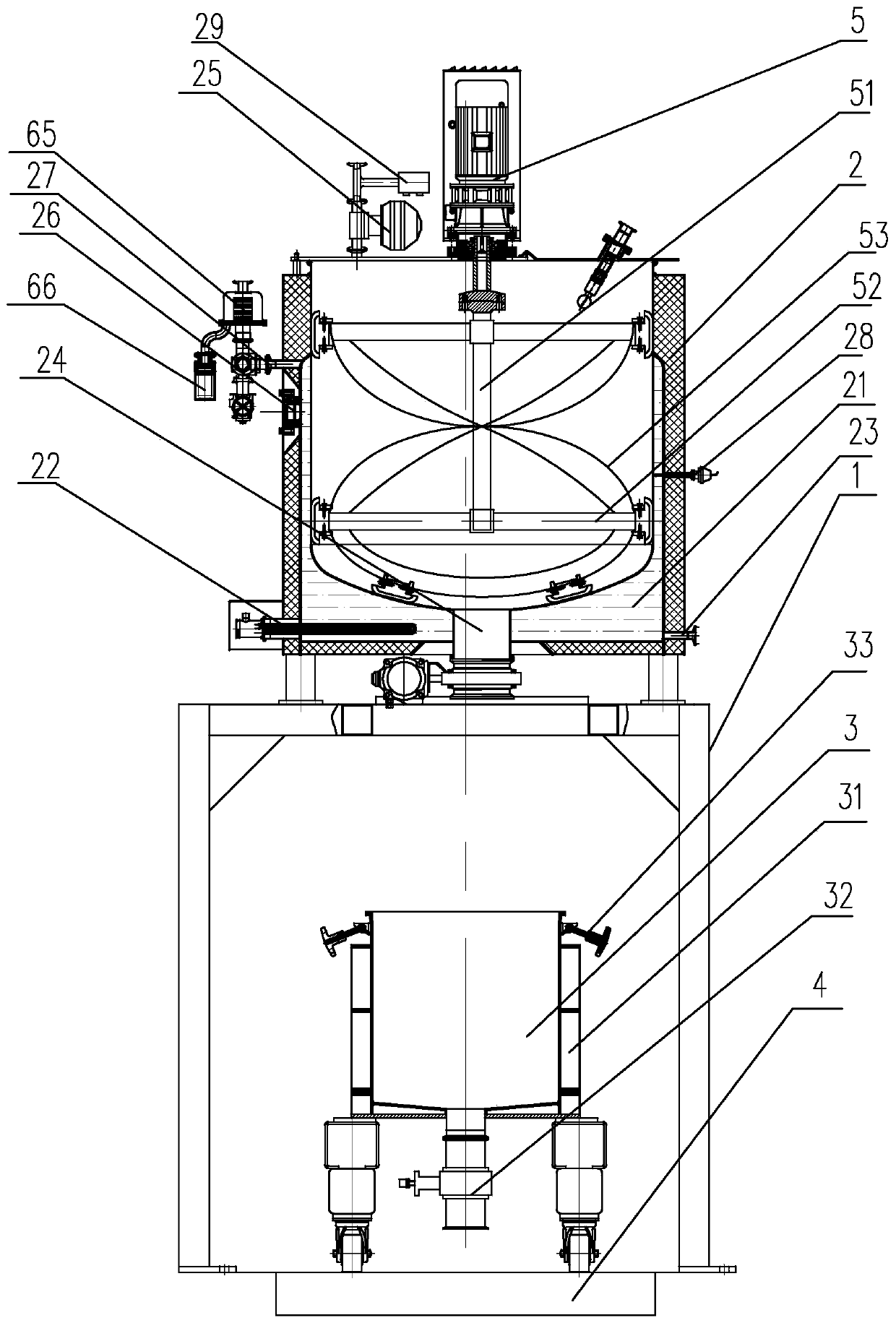
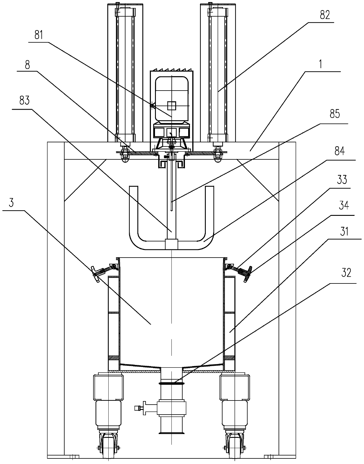
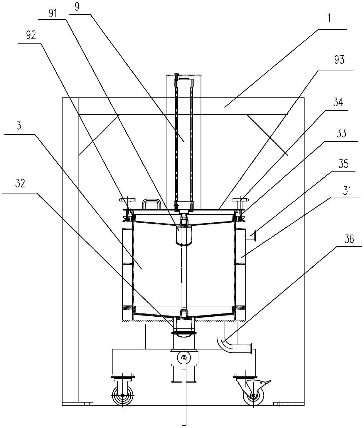
[0030] Depend on figure 1 , figure 2It can be seen that a slurry mixing device is disclosed, including a mounting frame 1, a slurry mixing tank 2, a slurry adding tank 3, a cooling mechanism and a slurry discharging mechanism, and the slurry mixing tank 2, the cooling mechanism and the slurry discharging mechanism are sequentially arranged on the installation On the frame 1, the installation frame 1 is provided with a conveying channel under the pulp distribution tank 2, the cooling mechanism and the pulp discharging mechanism, and the slurry adding tank 3 is opened and set in the conveying channel along the direction of the conveying channel. The conveying channel is provided with a mass scale 4 corresponding to the position of the mixing tank 2. A stirring chamber is formed in the mixing tank 2, and a stirring paddle is rotated in the mixing chamber. The mixing tank 2 is provided with a Rotating stirring motor 5, the bottom of the stirring chamber extends to the outside of...


PUM


Abstract

The invention discloses a pulp mixing device, which comprises a mounting frame, a pulp mixing tank, a pulp adding tank, a cooling mechanism and a pulp discharging mechanism, wherein a pulp adding tankis movably arranged below the pulp mixing tank, the cooling mechanism and the pulp discharging mechanism; a mass scale is arranged below the pulp adding tank; a stirring cavity is formed in the pulpmixing tank; a stirring valve is arranged in the stirring cavity; a stirring motor is arranged on the pulp mixing tank; a discharge port is arranged at the bottom of the stirring cavity; an oil bath cavity is formed between the pulp mixing tank and the stirring cavity; and the cooling mechanism comprises a lifting cylinder and a lifting seat. The lifting seat is provided with a rotating paddle anda rotating motor, the lifting cylinder is arranged on a mounting frame, the output end of the lifting cylinder is connected with the lifting seat, the pulp discharging mechanism comprises a piston and a driving cylinder, the piston is connected with the output end of the driving cylinder, the piston is provided with an elastic sealing ring along the circumferential direction, and the bottom of the pulp adding tank is provided with a pulp outlet. The pulp mixing device has simple structure, good pulp mixing effect, and simultaneously has the functions of conveying, cooling and extruding pulp,thereby improving the production and processing efficiency.

Description

technical field [0001] The invention relates to the technical field of slurry mixing equipment, in particular to a slurry mixing device. Background technique [0002] At present, in the production of pharmaceuticals and food, it is usually necessary to mix and mix powders. When mixing and mixing powders with a large consistency, the existing mixing tanks are in the process of gelatinization and maturation, and the stirring efficiency is not high, resulting in edge positions. Coking occurs in the slurry, and the existing mixing tank is usually heated by a water bath, and the heating temperature is insufficient. In the process of mixing a large volume of powder slurry, it cannot be fully heated, making the slurrying efficiency low, and it is not suitable for Large-volume slurry processing, at the same time, it is difficult to check the position of the heating fluid in the existing slurry mixing tank, and it is difficult to replenish it in time, or add it in place, reducing the...

Claims


Application Information

Patent Timeline
Patent Type & Authority Applications(China)
IPC IPC(8): B01F13/10B01F7/18B01F7/24B01F15/02B01F15/06B01F15/00
CPCB01F27/92B01F33/82B01F35/00B01F27/90B01F35/71B01F35/90B01F2035/98B01F35/92B01F2035/99B01F23/53B01F27/1122B01F27/1145B01F27/806B01F35/2117B01F27/922B01F35/2115B01F35/3204B01F35/21112B01F35/71805B01F35/75425B01F23/565
Inventor 方正陈建盈吴武通翁自正刘江海石力
Owner ZHEJIANG CANAAN TECH
Why Eureka
Try Eureka