Elevator safety device
A technology of elevator safety device and guide rail, applied in the field of elevator control, can solve the problems of increased complexity, inability to continuously adjust, and inability to apply safety devices, etc.
- Summary
- Abstract
- Description
- Claims
- Application Information
AI Technical Summary
Problems solved by technology
Method used
Image
Examples
Embodiment 1
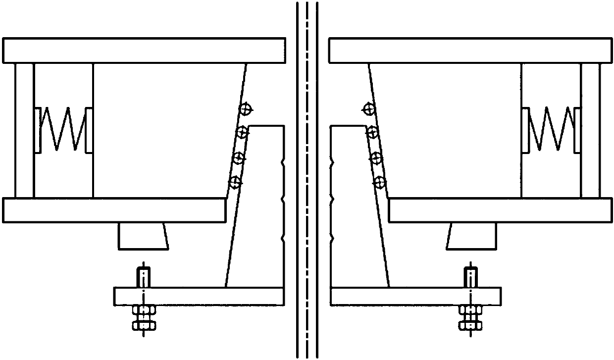
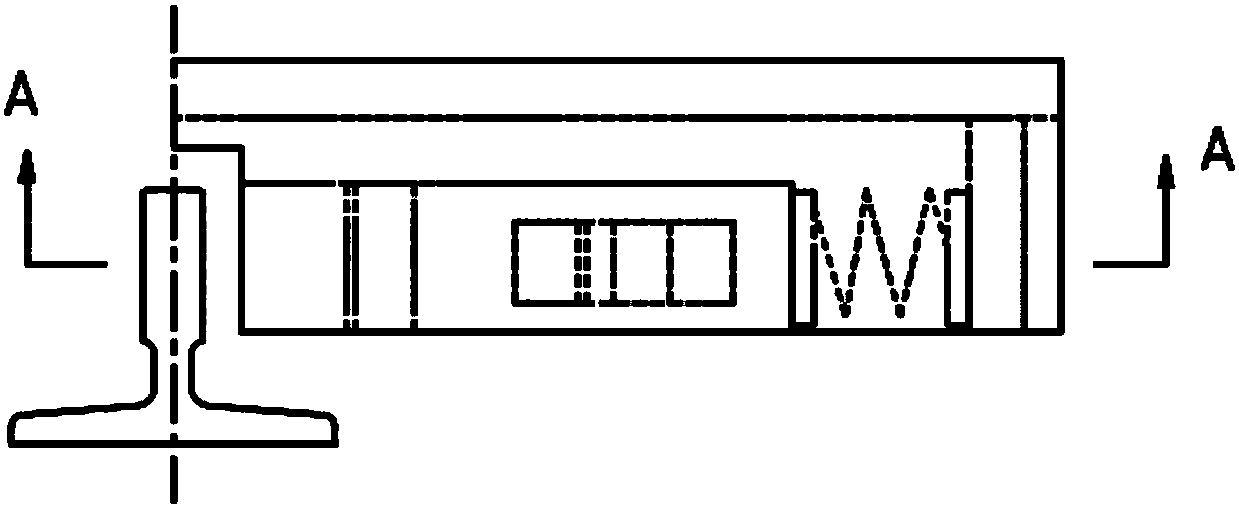
[0118] Such as figure 2 , image 3 , Figure 4 , Figure 5 and Figure 6 As shown, the elevator safety device includes a frame 1, a brake body 2, a guide body 3, a first elastic body 4, a limit wedge 5, and an adjustment wedge 6;
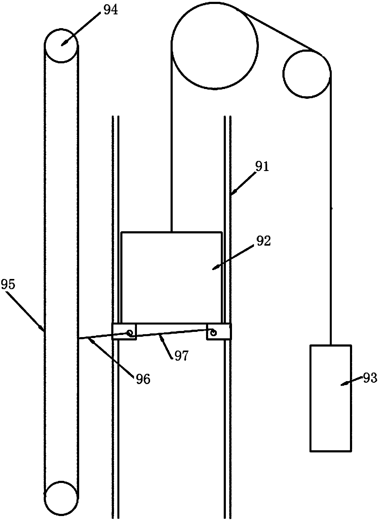
[0119] The frame 1 is used to be installed on the lifting body guided by the guide rail 91 arranged in the lifting channel, and the guide rail 91 is located in the approximate middle of one side of the frame 1;
[0120] The brake body 2 is suspended on the lifting body, and is located between the guide body 3 and the guide rail 91;
[0121] The brake body 2 is wedge-shaped with a narrow top and a wide bottom. The side near the guide rail 91 is a braking vertical surface 2a, and the side far from the guide rail 91 is a braking slope 2b;
[0122] The guide body 3 is arranged in the frame 1 and can move left and right along the frame 1;
[0123] Described guide body 3, its near guide rail side is the guide slope far away from the guide rail up and...
Embodiment 2
[0144] including such as Figure 7 Figure 8 As shown, the elevator safety device includes a frame 1, a brake body 2, a guide body 3, a first elastic body 4, a fixed limit plate 51, an adjustment wedge 6, and a guide wedge 31;
[0145] The frame 1 is used to be installed on the lifting body guided by the guide rail 91 arranged in the lifting passage, and the guide rail 91 is located in the middle of one side of the frame 1;
[0146] The brake body 2 is suspended on the lifting body, and is located between the guide body 3 and the guide rail 91;
[0147] The brake body 2 is wedge-shaped with a narrow top and a wide bottom. The side near the guide rail 91 is a braking vertical surface 2a, and the side far from the guide rail 91 is a braking slope 2b;
[0148] The guide body 3 is arranged in the frame 1 and can move left and right and up and down;
[0149] Described guide body 3, its near guide rail side is the guide slope far away from the guide rail up and down, and its far ...
Embodiment 3
[0171] Such as Figure 9 , Figure 10 As shown, the elevator safety device includes a frame 1, a brake body 2, a reverse wedge 61, a guide body 3, a first elastic body 4, a second elastic body 40, a connecting plate 42, and a limiting body 43;
[0172] The frame 1 is used to be installed on the lifting body guided by the guide rail 91 arranged in the lifting passage, and the guide rail 91 is located in the middle of one side of the frame 1;
[0173] The braking body 2 is suspended on the lifting body, and is located between the reverse wedge 61 and the guide rail 91;
[0174] The brake body 2 is wedge-shaped with a narrow top and a wide bottom. The side near the guide rail 91 is a braking vertical surface 2a, and the side far from the guide rail is a braking slope 2b;
[0175] The guide body 3 is arranged in the frame 1 and can move left and right along the frame;
[0176] Described guide body 3, its near guide rail side is the guide inclined plane far away from the guide r...
PUM
 Abstract
Description
Claims
Application Information
 - R&D
- Intellectual Property
- Life Sciences
- Materials
- Tech Scout
- Unparalleled Data Quality
- Higher Quality Content
- 60% Fewer Hallucinations
Browse by: Latest US Patents, China's latest patents, Technical Efficacy Thesaurus, Application Domain, Technology Topic, Popular Technical Reports.
© 2025 PatSnap. All rights reserved.Legal|Privacy policy|Modern Slavery Act Transparency Statement|Sitemap|About US| Contact US: help@patsnap.com


