
Low-height channel steel concrete composite beam

A channel-shaped steel, low-height technology, used in bridges, bridge parts, bridge materials, etc., can solve the problems of shortening the construction process, deviation of the line center line and bridge center line, etc., to shorten the construction process, improve the lateral stiffness, and facilitate the Modular pre-made effects

Pending Publication Date: 2020-09-08
SHIJIAZHUANG TIEDAO UNIV
View PDF6 Cites 0 Cited by
  • Summary
  • Abstract
  • Description
  • Claims
  • Application Information

AI Technical Summary

Problems solved by technology

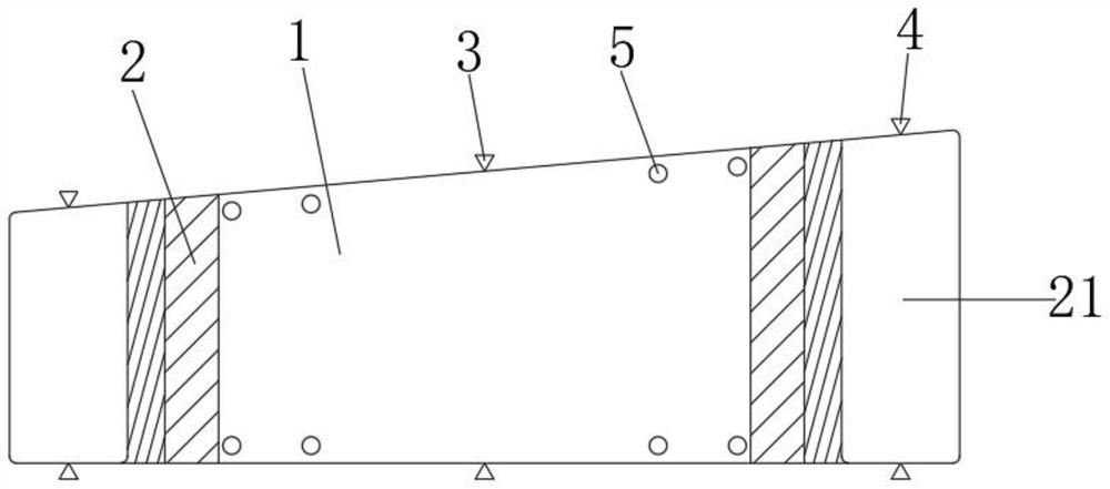
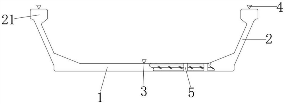
[0008] Aiming at the deficiencies of the prior art, the present invention provides a low-height trough-shaped steel-concrete composite beam, which has a high coincidence degree between the centerline of the line and the centerline of the bridge when the plane of the broken line is built. It has the advantages of simplifying the construction process and effectively improving work efficiency, and solves the problem that the center line of the line and the center line of the bridge deviate from each other for bridges with small curve radius existing in existing channel beams

Method used


Image

  • Low-height channel steel concrete composite beam
  • Low-height channel steel concrete composite beam
  • Low-height channel steel concrete composite beam

Examples


Embodiment Construction

[0027] A number of embodiments of the present invention will be disclosed in the following figures. For the sake of clarity, many practical details will be described together in the following description. It should be understood, however, that these practical details should not be used to limit the invention. That is, in some embodiments of the invention, these practical details are not necessary. In addition, for the sake of simplifying the drawings, some well-known and commonly used structures and components will be shown in a simple schematic manner in the drawings.

[0028] In addition, in the present invention, descriptions such as "first", "second" and so on are used for description purposes only, and do not refer to the meaning of order or sequence, nor are they used to limit the present invention, but are only for the purpose of distinguishing the following The components or operations described by the same technical terms are only used, but should not be understood a...


PUM


Abstract

The invention relates to the technical field of bridge construction. The utility model relates to a low-height channel steel concrete composite beam. The low-height channel steel concrete composite beam comprises a plurality of groove-shaped beam sections which are spliced with one another, each groove-shaped beam section comprises a bottom plate and a web plate; the upper end face of the bottom plate is in a trapezoid shape with one wide side inclined. Three linear theoretical control points are arranged on the plane where the sections on the two sides of the groove-shaped beam section are located, and the linear theoretical control points comprise the horizontal control point at the intersection point of the longitudinal center line of the upper end face of the bottom plate and the section of the bottom plate and the two elevation control points at the intersection point of the center lines of the upper end faces of the webs on the two sides and the section of the webs. Due to the fact that the upper end face of the bottom plate of each groove-shaped beam section is in the trapezoid shape with one wide side inclined, when a broken line plane is constructed, on the basis that it is guaranteed that the line center line coincides with the bridge center line and the bridge forming line is smooth, connecting parts do not need to be arranged between the adjacent groove-shaped beamsections, the construction process is shortened, and the working efficiency is effectively improved.

Description

technical field [0001] The invention relates to the technical field of bridge construction, in particular to a low-height channel-shaped steel-concrete composite beam. Background technique [0002] With the rapid growth of my country's economy, my country's rail transit construction is also developing at a high speed. In terms of construction cost, viaducts or overpasses are often the first choice for rail transit construction. At present, channel girder and box girder are two types of girder structures commonly used in erecting viaducts. [0003] The prior art generally adopts the whole hole prefabricated box girder or channel girder structure as the technical basis for viaduct erection. Such as Figure 5 As shown, the whole hole prefabricated traditional beam structure 7 is a kind of prefabricated whole hole in the prefabrication factory according to the capacity of the lifting installation equipment, and then the whole hole prefabricated beam structure 7 is installed on...

Claims


Application Information

Patent Timeline
Patent Type & Authority Applications(China)
IPC IPC(8): E01D2/00E01D19/00E01D101/26
CPCE01D2/00E01D19/00E01D2101/26
Inventor 卜建清曹文龙刘勤庞志强镇顺利王迪臧朔
Owner SHIJIAZHUANG TIEDAO UNIV
Learn More