
A sealing valve installation structure and no-cleaning washing machine

An installation structure and sealing valve technology, applied in the field of washing machines, can solve the problems of inability to clean, easy to accumulate dirt, unable to expand the washing capacity of the washing machine, etc., and achieve the effect of ensuring prying rotation and installation and fixation

Active Publication Date: 2021-09-07
QINGDAO JIAONAN HAIER WASHING MACHINE +2
View PDF10 Cites 0 Cited by
  • Summary
  • Abstract
  • Description
  • Claims
  • Application Information

AI Technical Summary

Problems solved by technology

[0003] However, since the inner cylinder and the outer cylinder are interfitted with each other, dirt is easy to accumulate between the inner and outer cylinders during the use of the washing machine; at the same time, because the inner and outer cylinders are intertwined, the user cannot clean the outer wall of the inner cylinder and the inner wall of the outer cylinder, which increases the number of bacteria in the washing machine , reducing the washing efficiency of the washing machine and the cleanliness of the clothes after washing
[0004] Simultaneously, in the above-mentioned existing washing machine, because the inner cylinder is equipped with an outer cylinder, the washing process of the washing machine is to beat and wash the clothes through the rotation of the inner cylinder, so that the washing capacity of the washing machine is based on the inner cylinder, so that the internal space utilization rate of the washing machine is Low, unable to expand the washing capacity of the washing machine on the existing basis
[0005] In view of this, how to set up a washing machine to combine the inner and outer cylinders into one, or directly set up a closed inner cylinder, so that the inner cylinder can be set as a sealed container, which can hold water and clothes, and can rotate and beat the clothes for washing. It avoids the problem that the washing water needs to be cleaned between the inner and outer cylinders when the washing water flows between the inner and outer cylinders; at the same time, since the outer cylinder can also be installed on the washing machine, or the outer cylinder and the washing machine shell can be integrated, the washing machine can also be used The expansion of the inner cylinder to expand the washing capacity of the washing machine has become a research and development hotspot

Method used


Image

  • A sealing valve installation structure and no-cleaning washing machine
  • A sealing valve installation structure and no-cleaning washing machine
  • A sealing valve installation structure and no-cleaning washing machine

Examples


Embodiment 1

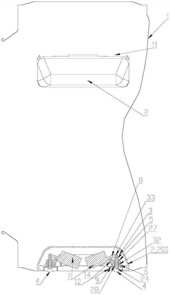
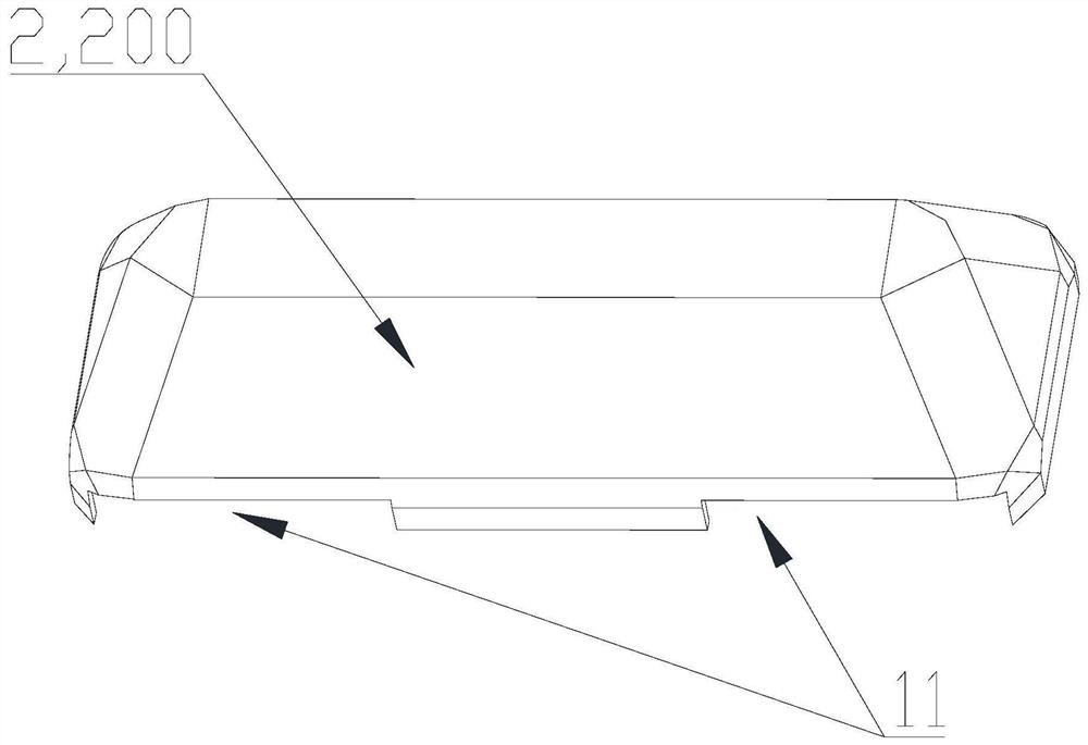
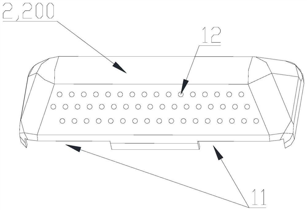
[0044] Such as Figure 1 to Figure 5 As shown, this embodiment introduces a lifting rib structure of the inner tube for the above-mentioned no-cleaning washing machine. The inner tube lifting rib 2 includes a lifting rib body 200 extending along the inner tube side wall construction line. The shell structure is open on the side and fastened to the inner wall of the inner cylinder 1. The interior of the lifting rib body 200 is hollow to form the installation cavity 3 for the installation of the sealing valve. into the water structure in the installation cavity 3.

[0045] By setting the lifting rib of the inner cylinder as a hollow chamber, the inside of the lifting rib forms a chamber for the installation of the water supply and drainage sealing valve, thereby achieving the concealed assembly of the sealing valve and realizing the function of the non-cleaning washing machine using centrifugal force to drain water; at the same time, the lifting The ribs extend along the constr...

Embodiment 2

[0059] Such as Figure 1 to Figure 7 As shown, this embodiment introduces a sealing valve installation structure for the above-mentioned no-cleaning washing machine. The sealing valve installation structure includes a support plate 9 installed on the inner wall of the inner cylinder 1. The middle part of the support plate 9 is provided with a The through hole 23 corresponding to the outlet 4 on the side wall of the cylinder 1, the support plate 9 and the side wall of the inner cylinder 1 are separated by a certain gap to form a space for the spool of the sealing valve to move up and down; the upper side of the support plate 9 is fixed A sleeve-shaped installation sleeve 6 is installed, and the inner through hole of the installation sleeve 6 is coaxially arranged opposite to the through hole 23 provided on the support plate 9, so that the spool of the sealing valve can be installed coaxially and movable up and down on the inner through hole. in the hole.

[0060] By setting th...

Embodiment 3

[0071] Such as Figure 1 to Figure 7 As shown, in this embodiment, a sealing valve plug structure for the above-mentioned no-cleaning washing machine is introduced, and the sealing valve core structure includes a valve plug column 5 correspondingly installed on the drain port provided on the side wall of the inner cylinder 1, and A counterweight 7 hinged at the upper end of the valve plug post 5 ; a sealing valve installation structure is fixedly installed on the side wall of the inner tube 1 , and a return spring 32 is sandwiched between the sealing valve installation structure and the valve plug post 5 .


PUM


Abstract

The invention relates to a sealing valve installation structure, which comprises a support plate installed on the inner side wall of the inner cylinder. There is a certain gap between them to form a space for the spool of the sealing valve to move up and down; a sleeve-shaped installation sleeve is fixedly installed on the upper side of the support plate, and the inner through hole of the installation sleeve is coaxially set opposite to the through hole set on the support plate. , to install the spool of the sealing valve coaxially and movable up and down in the inner through hole. The present invention also provides a no-cleaning washing machine. The inner tub of the washing machine is a container whose opening is fastened by a door cover, and at least one drain outlet connected to the hollow part of the lifting rib is provided on the side wall of the inner tub. The sealing valve inside the lifting rib is installed on the inner cylinder through the above-mentioned installation structure.

Description

technical field [0001] The invention belongs to the technical field of washing machines, and in particular relates to a washing machine with only a rotatable and water-holding inner cylinder, and also provides a sealing valve installation structure applied to the washing machine. Background technique [0002] In the prior art, a drum washing machine generally includes an inner cylinder and an outer cylinder that fit each other, the outer cylinder is sealed to hold water, the inner cylinder is used to hold clothes, and the inner cylinder is rotated to beat and wash the clothes; at the same time, the inner cylinder is Set the dehydration hole so that the water in the outer cylinder flows into the inner cylinder through the dehydration hole to soak the clothes in the inner cylinder, the water in the inner cylinder flows out to the outer cylinder through the dehydration hole, and the moisture on the clothes in the inner cylinder is dehydrated when the inner cylinder rotates at hi...

Claims


Application Information

Patent Timeline
Patent Type & Authority Patents(China)
IPC IPC(8): D06F39/08D06F37/02
CPCD06F39/083D06F37/02D06F23/025D06F37/065D06F37/06F16K27/02F16K31/52
Inventor 李以民劳春峰郝兴慧吴迪吕佩师
Owner QINGDAO JIAONAN HAIER WASHING MACHINE
Learn More