Air-leakage-proof dry-blowing casing device and method

A leak-proof, casing technology, applied in the direction of drying gas arrangement, drying, dryer, etc., can solve the problems of easy falling off, easy to swing up and down, damage to casing, etc., to achieve uniform dry blowing effect, avoid wrinkles, increase The effect of lubricity

Active Publication Date: 2021-10-26
东莞市德鸿肠衣有限公司
View PDF8 Cites 0 Cited by
  • Summary
  • Abstract
  • Description
  • Claims
  • Application Information

AI Technical Summary

Problems solved by technology

[0004] The purpose of the present invention is to solve the dry blowing casing method on the market, which is to directly install one end of the casing on the air outlet of the dry blowing equipment. Since the casing is relatively lubricated, the friction between the two is small, and it is difficult to dock. , during the dry blowing process, the casing is easy to fall off, and the casing is easy to swing up and down under the blowing force, which is easy to cause damage to the casing, and a leak-proof dry blowing casing device and method are proposed

Method used


Image

  • Air-leakage-proof dry-blowing casing device and method
  • Air-leakage-proof dry-blowing casing device and method
  • Air-leakage-proof dry-blowing casing device and method

Examples


Embodiment 1

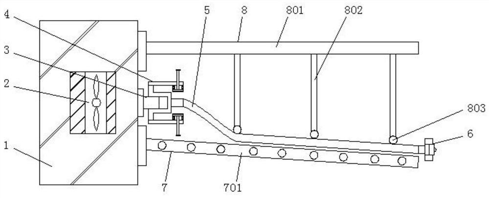
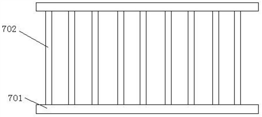
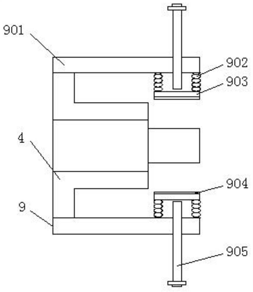
[0044] see Figure 1-4 , a leak-proof dry-blowing casing device and method, comprising a main box 1, a support mechanism 7 and a sealing mechanism 9, a fan 2 is arranged inside the main box 1, and an air outlet 3 is arranged on one side of the main box 1, One side of the air outlet 3 is inlaid with a connecting terminal 4, and one end of the connecting terminal 4 is connected with a casing 5, and one end of the casing 5 is installed with a gas-blocking terminal 6, and the inside of the gas-blocking terminal 6 is provided with an air outlet channel 601 , a sealing plug 602 is placed on one side of the air outlet channel 601, the support mechanism 7 is fixed on the upper end of one side of the main box 1, and the other upper end of the main box 1 is inlaid with a compression mechanism 8, and the sealing mechanism 9 is connected to the connecting end Outer side of head 4.

[0045] see figure 1 and 4 , the sealing plug 602 is flexibly connected to the air-blocking terminal 6, a...

Embodiment 2

[0050] Casing 5 carding: First, separate the entangled casings 5 ​​from each other, and untie the single knotted or adhered casings 5, then pick up one end of the casing 5 and shake it to keep the casing 5 vertical down.

[0051] The steps of casing 5 sealing connection are:

[0052] Step 1. Soak the inlet end and the outlet end of the casing 5 in hot water for ten minutes;

[0053] Step 2: After the inlet end and outlet end of the casing 5 are softened, insert the outlet end of the connection end 4 into the inlet end of the casing 5, and rotate the upper and lower threaded rods 905 at the same time. 903 forms extrusion until the sealing ring 904 presses the casing 5 against the outer wall of the outlet end of the connecting terminal 4 , and then inserts the connecting terminal 4 into the air outlet 3 .

[0054] Step 3: Insert the inlet end of the gas blocking terminal 6 into the outlet end of the casing 5 , and insert the sealing plug 602 into the gas outlet channel 601 in ...


PUM


Abstract

The invention discloses an air-leakage-proof dry-blowing casing device and method, which relate to the technical field of casing processing and include a main box, a supporting mechanism and a sealing mechanism. A fan is arranged inside the main box, and one side of the main box is arranged There is an air outlet, one side of the air outlet is inlaid with a connecting end, and one end of the connecting end is connected with a casing, one end of the casing is installed with an air-blocking end, and the inside of the air-blocking end is provided with an air outlet channel , the inner side of the air outlet channel is provided with a sealing plug, the support mechanism is fixed on the upper end of one side of the main box, and the other upper end of the main box is inlaid with a pressing mechanism. In the present invention, the casings are first combed to prevent the casings from being entangled together, which will affect the dry blowing effect of the casings. Oil, avoid oil to increase the lubrication of the casing and make the connection between the casing and the end more tightly.

Description

technical field [0001] The invention relates to the technical field of casing processing, in particular to an air-leakage-proof dry blowing casing device and method. Background technique [0002] Casing is a livestock product scraped from the large and small intestines of livestock. It is mainly used as a coat for filling sausages and enemas; sheep casings can also be made into guts for making tennis racket strings, bowstrings and surgical sutures. After the casing is scraped, the casing needs to be processed. First, the casing is cleaned, and then the casing is dried. In order to speed up the treatment of the casing, a method and device for drying the casing are needed. [0003] The method of dry blowing casings on the market is to directly install one end of the casing on the air outlet of the dry blowing equipment. Since the casing is relatively lubricated, the friction between the two is small, and it is difficult to connect. During the dry blowing process, The casing i...

Claims


Application Information

Patent Timeline
Patent Type & Authority Patents(China)
IPC IPC(8): A22C17/14F26B21/00F26B25/00
CPCA22C17/14F26B21/004F26B25/001
Inventor 蒋爱华
Owner 东莞市德鸿肠衣有限公司
Why Eureka
Try Eureka