Cable winding device used for electric power engineering

A winding device and power engineering technology, applied in hoisting devices, cable laying equipment, transportation and packaging, etc., can solve the problems of heavy drum weight and inconvenient unloading, and achieve the effect of convenient disassembly and installation, labor saving and stability assurance

Inactive Publication Date: 2019-09-06
海鹏建设有限公司
View PDF16 Cites 10 Cited by
  • Summary
  • Abstract
  • Description
  • Claims
  • Application Information

AI Technical Summary

Problems solved by technology

[0004] The purpose of the present invention is: in order to solve the problem that the drum of the existing cable winding device is heavy and inconvenient to unload after being fully loaded, the present invention provides a cable winding device for electric power engineering

Method used


Image

  • Cable winding device used for electric power engineering
  • Cable winding device used for electric power engineering
  • Cable winding device used for electric power engineering

Examples


Embodiment 1

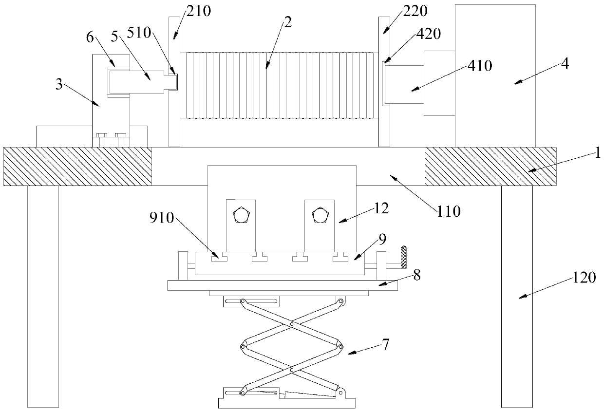
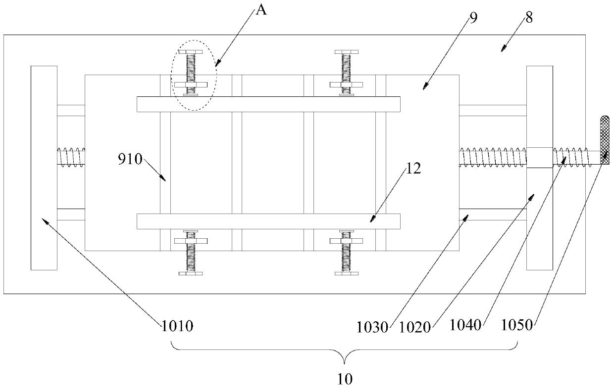
[0028] The cable winding device for electric power engineering of the present invention comprises a placing table 1, a plurality of legs 120 are arranged at the lower end of the placing table 1, a through groove 110 is opened in the middle of the placing table 1, and a roller 2 is arranged above the through groove 110, The left and right sides of the drum 2 are respectively connected with a first turntable 210 and a second turntable 220, and the left and right sides of the through groove 110 are respectively provided with a slide seat 3 and a drive motor 4, the slide seat 3 can move left and right, and the slide seat 3 and the first turntable The driven shaft 5 is connected between the turntables 210, and the drive shaft 410 of the drive motor 4 is connected to the second turntable 220. A lifting plate 8 is provided below the through groove 110, and a lifting drive device 7 is provided at the lower end of the lifting plate 8. The upper end of the plate 8 is provided with an adj...

Embodiment 2

[0031] This embodiment is further optimized on the basis of Embodiment 1 as follows: the middle part of the first turntable 210 is provided with a first positioning groove 510, the middle part of the second turntable 220 is provided with a second positioning groove 420, and the upper end of the slide seat 3 A bearing 6 is provided, one end of the driven shaft 5 is rotationally connected with the bearing 6 , and the other end of the driven shaft 5 is interference fit with the first positioning groove 510 ; the driving shaft 410 is interference fit with the second positioning groove 420 .

[0032] After adopting the above technical solution, the first turntable 210 is provided with a first positioning groove 510, the second turntable 220 is provided with a second positioning groove 420, the driven shaft 5 and the first positioning groove 510 and the driving shaft 410 and the second positioning groove 420 Both are interference fits. When installing the drum 2, the installation is ...

Embodiment 3

[0034]This embodiment is further optimized on the basis of Embodiment 1 as follows: the upper end of the placing table 1 is provided with a slide block 310, the lower end of the slide seat 3 is provided with a chute matching with the slide block 310, the two sides of the slide block 310 There are a plurality of positioning holes 320 on the side, and a plurality of bolt assemblies 330 matching with the positioning holes 320 are arranged on both sides of the sliding seat 3 . The slide block 310 is a dovetail block, and the chute is a dovetail groove adapted to the dovetail block.

[0035] After adopting the above technical solution, the sliding seat 3 can move left and right through the slider 310, and then realize the left and right movement of the driven shaft 5, so that the driven shaft 5 can enter the first positioning groove 510 in the process of moving to the right, and When dismounting, the sliding seat 3 first moves away from the roller 2, and the sliding seat 3 and the ...


PUM


Abstract

The invention discloses a cable winding device used for electric power engineering and belongs to the technical field of electric power engineering devices. The device is used for solving the problemthat a roller of an existing cable winding device is large in weight and inconvenient to unload after being fully loaded. The cable winding device comprises a holding table. A plurality of supportinglegs are arranged at the lower end of the holding table. A through groove is formed in the middle of the holding table in a penetrating mode. A roller is arranged above the through groove. The left and right sides of the roller are connected with a first turnplate and a second turnplate correspondingly. A sliding base and a driving motor are arranged on the left and right sides of the through groove correspondingly. The sliding base can move left and right. A driven shaft is connected between the sliding base and the first turnplate. A driving shaft of the driving motor is connected with the second turnplate. A lifting plate is arranged below the through groove. A lifting driving device is arranged at the lower end of the lifting plate. An adjusting plate is arranged at the upper end of the lifting plate and connected with a lead screw transmission unit.

Description

technical field [0001] The invention relates to the technical field of electric power engineering devices, in particular to a cable winding device for electric power engineering. Background technique [0002] Electric power engineering refers to engineering related to the production, transmission, and distribution of electric energy. In a broad sense, it also includes engineering that uses electricity as power and energy in various fields. The transmission and distribution of electric energy is mainly realized through high and low voltage AC power grids. The use of electric energy has penetrated into all areas of the national economy and people's lives, and has become the main power form of industry, agriculture, transportation and national defense and indispensable in people's family life. It has been widely used in traction, lighting, electric heating, electrochemistry and communication. The transmission of electric energy is inseparable from cables, and cables mainly tra...

Claims


Application Information

Patent Timeline
Patent Type & Authority Applications(China)
IPC IPC(8): B65H54/553B65H54/70B65H67/04H02G1/06B66F7/06B66F7/28
CPCB65H54/553B65H54/70B65H67/0411B65H67/0417B65H2701/34B66F7/0666B66F7/28H02G1/06
Inventor 胡利苹刘亚楠
Owner 海鹏建设有限公司
Why Eureka
Try Eureka