Debris flow area bridge pier with floating anti-collision device

An anti-collision device and debris flow technology, applied in bridges, bridge parts, bridge construction, etc., can solve the problems of poor energy absorption effect of anti-collision devices, limited protection height of anti-collision devices, and the threat of debris flow disasters on bridges, so as to improve the anti-collision device. performance, impact reduction effect

Active Publication Date: 2019-09-06
CHONGQING JIAOTONG UNIVERSITY
View PDF18 Cites 1 Cited by
  • Summary
  • Abstract
  • Description
  • Claims
  • Application Information

AI Technical Summary

Problems solved by technology

[0002] my country is a country with frequent occurrence of debris flow disasters, and bridges located in debris flow areas are often threatened by debris flow disasters; in order to protect bridges in debris flow areas, the most common means is to set up anti-collision devices such as protective sleeves on bridge piers, and use anti-collision devices to buffer the impact of debris flow Function; the existing problem is: most of the existing anti-collision devices adopt fix...

Method used


Image

  • Debris flow area bridge pier with floating anti-collision device
  • Debris flow area bridge pier with floating anti-collision device

Examples


Embodiment Construction

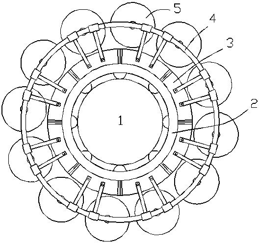
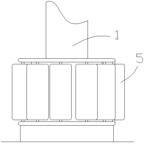
[0015] A bridge pier in a debris flow area with a floating anti-collision device, the innovation of which is: the bridge pier in the debris flow area is composed of a pier body 1, a buffer sleeve 2, a pontoon ring 3, a connecting frame 4 and a plurality of anti-collision barrels 5;

[0016] The buffer sleeve 2 is a cylindrical structure, and the inner hole wall of the buffer sleeve 2 is provided with a plurality of spherical protrusions; the buffer sleeve 2 is sleeved on the pier body 1, and the spherical protrusions are in contact with the outer wall of the pier body 1;

[0017] The buoyant ring 3 is an annular structure formed by connecting a plurality of buoyant tanks, the buoyant ring 3 is sleeved outside the buffer sleeve 2, and the buoyant ring 3 is fixedly connected to the outer wall of the buffer sleeve 2;

[0018] The connecting frame 4 includes an upper bracket, a lower bracket, a plurality of upper connecting rods, a plurality of lower connecting rods and a plurality...


PUM


Abstract

The invention discloses a debris flow area bridge pier with a floating anti-collision device. The debris flow area bridge pier is composed of a pier body, a buffer sleeve, a buoyancy box ring, a connecting frame and a plurality of anti-collision barrels. The debris flow area bridge pier with the floating anti-collision device has the beneficial technical effects that according to the scheme, the impact effect of debris flow on a bridge can be effectively reduced, and the anti-collision performance of the debris flow area bridge is improved.

Description

technical field [0001] The invention relates to a bridge pier protection technology, in particular to a bridge pier in a debris flow area with a floating anti-collision device. Background technique [0002] my country is a country with frequent occurrence of debris flow disasters, and bridges located in debris flow areas are often threatened by debris flow disasters; in order to protect bridges in debris flow areas, the most common means is to set up anti-collision devices such as protective sleeves on bridge piers, and use anti-collision devices to buffer the impact of debris flow Function; the existing problem is: most of the existing anti-collision devices adopt fixed installation methods, and the protection height of the anti-collision devices is limited. In addition, the existing anti-collision devices have poor energy absorption effect and the protection effect is not ideal; in addition, the existing anti-collision devices are generally close to the pier, and the surface...

Claims


Application Information

Patent Timeline
IPC IPC(8): E01D19/02
CPCE01D19/02
Inventor 任青阳林小砜陈斌韩振雷刘洋
Owner CHONGQING JIAOTONG UNIVERSITY
Why Eureka
Try Eureka