A Gravity Vertical Retaining Wall Structure

A kind of retaining wall, gravity type technology, applied in the direction of underwater structure, infrastructure engineering, construction, etc., can solve the problem of unable to reinforce the retaining wall, unable to assist the construction personnel to increase the cross-sectional area of ​​the lower end, gravity type retaining wall construction Cumbersome and other problems, to achieve the effect of increasing the cross-sectional area and increasing the stability

Active Publication Date: 2021-10-15
元启建设集团有限公司 +1
View PDF6 Cites 0 Cited by
  • Summary
  • Abstract
  • Description
  • Claims
  • Application Information

AI Technical Summary

Problems solved by technology

[0007] In order to solve the above-mentioned technical problems, the present invention provides a gravity type vertical retaining wall structure to solve the problem that the existing gravity type retaining wall has a relatively simple structure, so that the construction of the existing gravity type retaining wall is also relatively simple compared with other types of retaining walls. The wall is convenient, and the existing gravity retaining wall requires a balance between the height of the upper end and the cross-sectional area of ​​the lower end. When the height of the upper end is increased, the existing gravity retaining wall cannot assist the construction personnel to increase the cross-sectional area of ​​the lower end. The lower end of the wall is placed inside the soil, which makes the construction of the gravity retaining wall more cumbersome when increasing the cross-sectional area, and the existing retaining wall cannot be reinforced inside the retaining wall when the height is increased after long-term use

Method used


Image

  • A Gravity Vertical Retaining Wall Structure
  • A Gravity Vertical Retaining Wall Structure
  • A Gravity Vertical Retaining Wall Structure

Examples


Embodiment

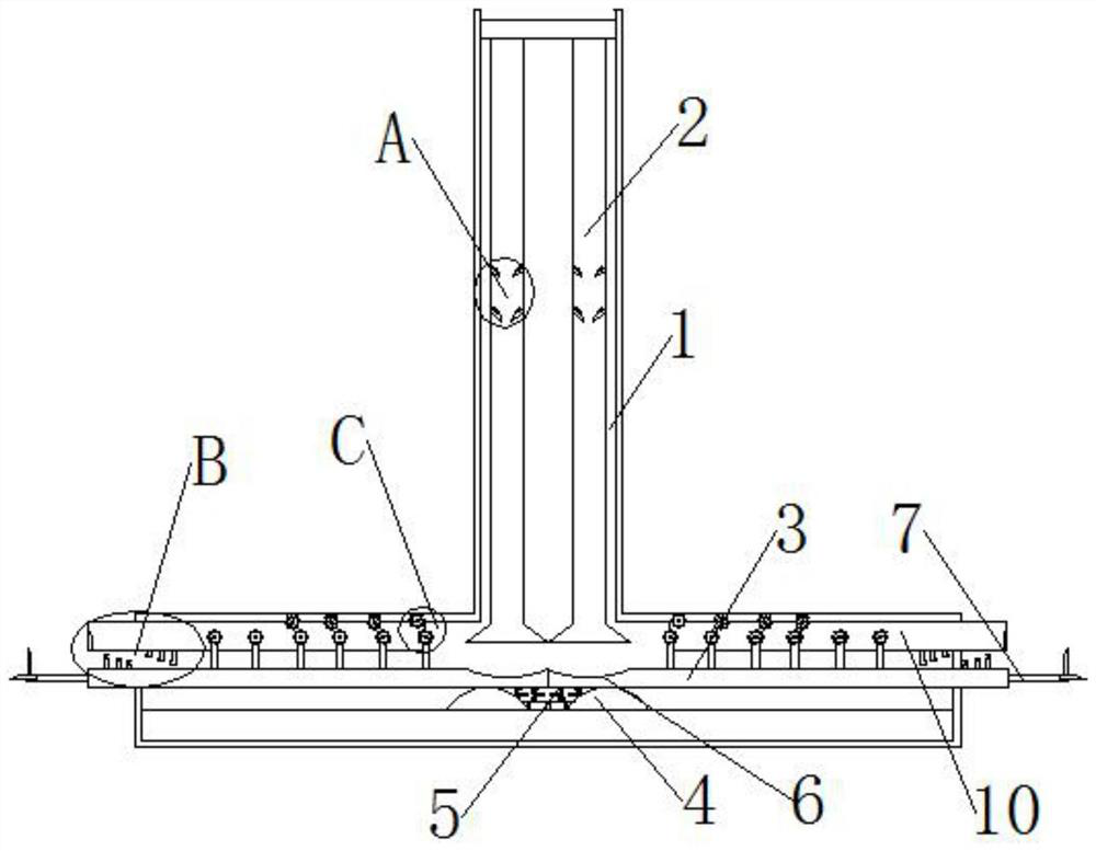
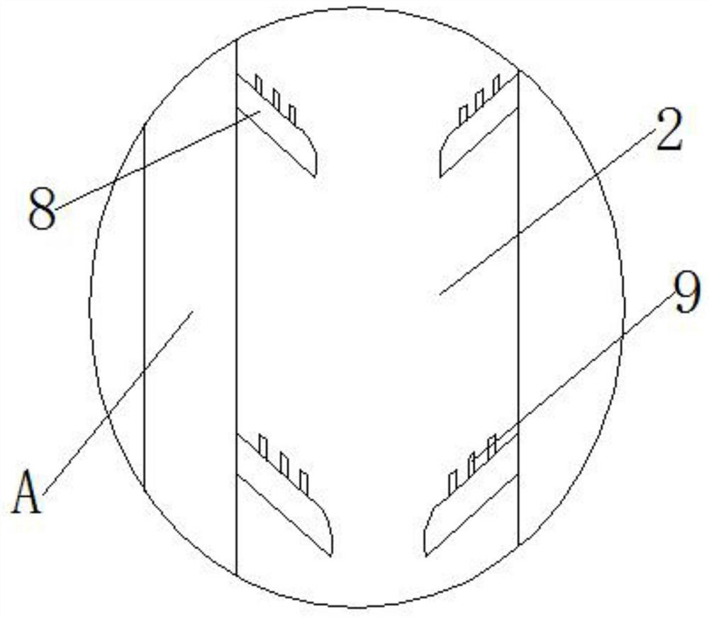
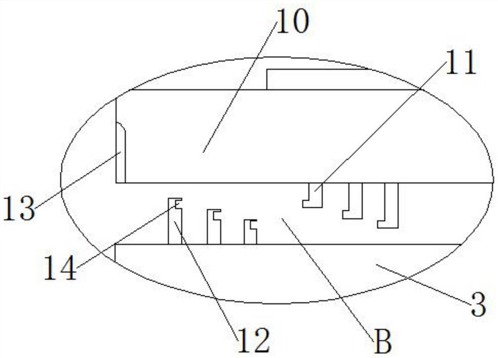
[0029] as attached figure 1 to attach Figure 6 Shown: a gravity-type vertical retaining wall structure, including a wall 1, the interior of the wall 1 is provided with a through pipe 2, the interior of the through pipe 2 is provided with a deceleration plate 8, and one end of the deceleration plate 8 is provided with a deceleration block 9, One end of the body of wall 1 is provided with a rotating plate 3, one end of the rotating plate 3 is provided with a rotating ball 4, one side of the rotating ball 4 is provided with a spring 5, one side of the rotating plate 3 is embedded with a rotating groove 6, and one end of the rotating plate 3 There is a lower docking frame 12, one side of the lower docking frame 12 is provided with a docking groove 14, one end of the rotating plate 3 is provided with a support rod 16, one end of the support rod 16 is provided with a gear 15, and one side of the gear 15 is provided with a pulley 17 The outside of the gear 15 and the pulley 17 is p...


PUM


Abstract

The invention provides a gravity-type upright retaining wall structure, which includes a wall body, a through pipe is arranged inside the wall body, a deceleration plate is arranged inside the through pipe, a deceleration block is provided at one end of the deceleration plate, and a rotating One end of the rotating plate is provided with a rotating ball, one side of the rotating ball is provided with a spring, one side of the rotating plate is embedded with a rotating groove, and one end of the rotating plate is provided with a lower docking frame. When gravity causes the rotating plate to rotate, the rotating plate can drive the gear to move vertically, and the gear can drive the pulley to rotate, so that the pulley can drive the extension plate to move horizontally, and the gear can move up and down repeatedly. , the friction force between the gear and the pulley can be reduced when the gear moves downward through the through block.

Description

technical field [0001] The invention belongs to the technical field of retaining walls, in particular to a gravity-type upright retaining wall. Background technique [0002] The retaining wall refers to the structure that supports the subgrade filling or hillside soil and prevents the deformation and instability of the filling or soil. The gravity retaining wall is usually set in an inverted "T" shape, and the size of the gravity retaining wall varies with the wall. When the height of the wall needs to be changed, the cross-sectional area of ​​the lower end of the retaining wall in contact with the ground needs to be changed to ensure the vertical balance of the gravity retaining wall. [0003] For example, the patent application number CN201810081309.6 discloses a T-shaped retaining wall, including a retaining wall, the bottom of the retaining wall is provided with a retaining wall base, and the retaining wall is fixedly connected to the One side of the base of the retaini...

Claims


Application Information

Patent Timeline
Patent Type & Authority Patents(China)
IPC IPC(8): E02D29/02
CPCE02D29/02
Inventor 吴东波
Owner 元启建设集团有限公司
Why Eureka
Try Eureka