a shut-off valve

A shut-off valve and control component technology, applied in the field of shut-off valves, can solve the problems of easy bending of live wires and control rods, affecting the normal process of pipeline transportation, etc., so as to avoid pressure bending and live wires, and increase flexibility. Effect

Active Publication Date: 2020-12-08
ZHUJI HAIDAO MACHINERY CO LTD
View PDF8 Cites 1 Cited by
  • Summary
  • Abstract
  • Description
  • Claims
  • Application Information

AI Technical Summary

Problems solved by technology

[0003] Problem 1: The control rod of the existing stop valve is threaded to the valve body. When the stop valve is buried underground and under pressure, the control rod of the stop valve is prone to bending and live wires;
[0004] Problem 2: The turntable of the existing stop valve is fixedly connected to the control rod. When the stop valve is placed against the wall and exposed on the surface, it is easy to be turned by non-operators, which affects the normal process of pipeline transportation.
[0005] For the problems listed above, there is no better exploration and practice results under the existing technical conditions. Therefore, it is necessary to do further exploration and practice to solve the problems listed above

Method used


Image

  • a shut-off valve
  • a shut-off valve
  • a shut-off valve

Examples


Embodiment Construction

[0022] Embodiments of the present invention will be described below with reference to the drawings. In the process, in order to ensure the clarity and convenience of illustration, we may exaggerate the width of the lines or the size of the constituent elements in the diagram.

[0023] In addition, the following terms are defined based on the functions in the present invention, and may be different according to the user's or operator's intention or practice. Therefore, these terms are defined based on the entire content of this specification.

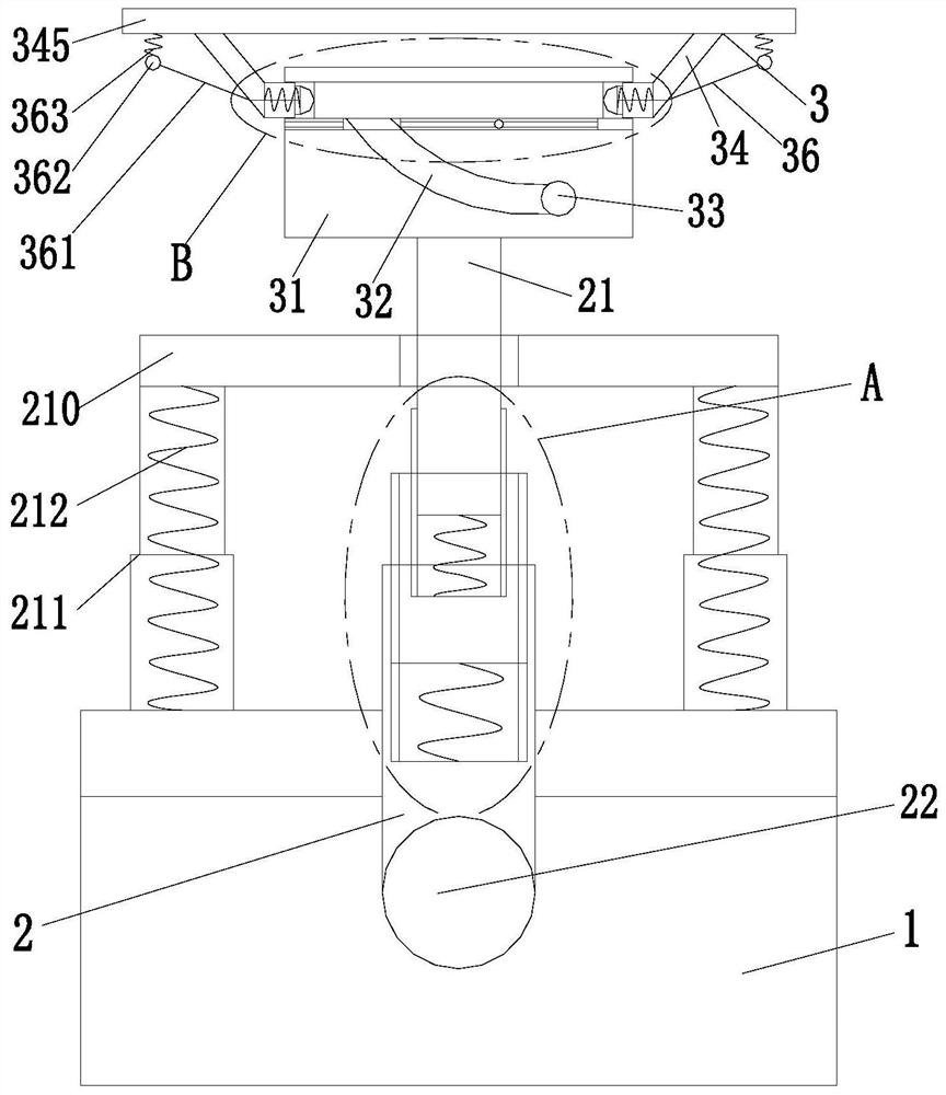
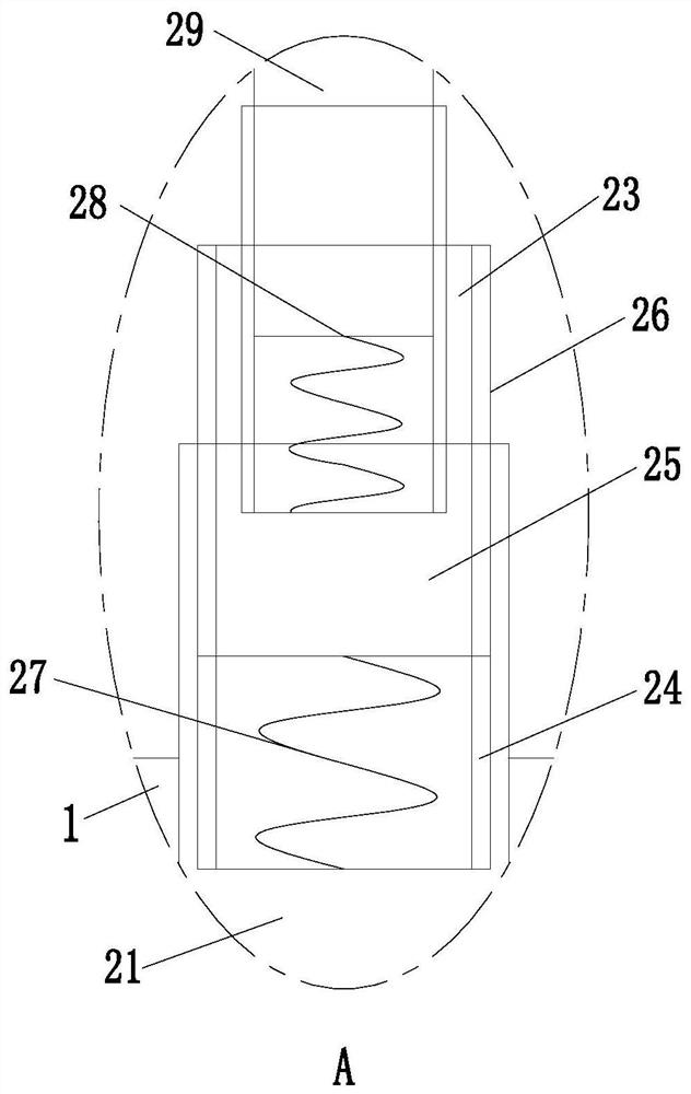
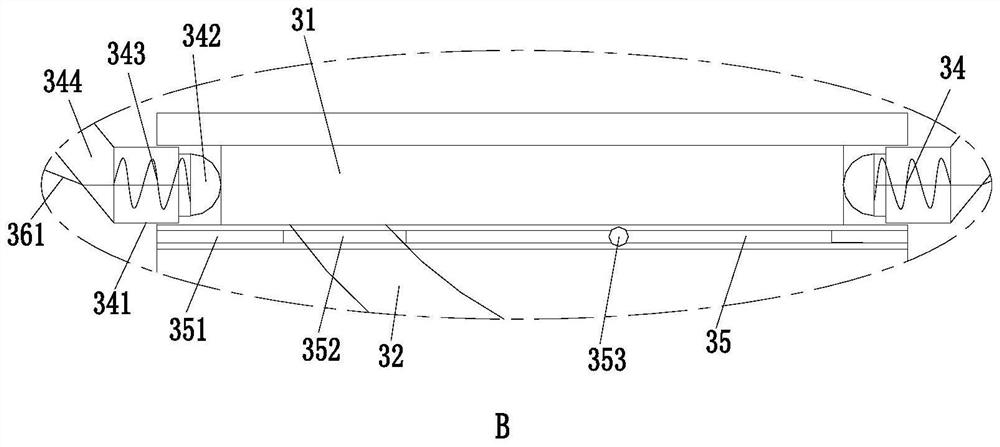
[0024] Such as Figure 1 to Figure 3 As shown, a shut-off valve includes a connecting pipe 1, a control assembly 2 and a rotating assembly 3. The upper end of the connecting pipe 1 is threaded with the control assembly 2, and the upper end of the control assembly 2 is installed with the rotating assembly 3.

[0025] The rotating assembly 3 includes a rotating seat 31 installed on the upper end surface of the control assembly 2, the upp...


PUM


Abstract

The invention relates to a stop valve. The stop valve comprises a connecting pipe, a control assembly and a rotating assembly; the upper end of the connecting pipe is in threaded connection with the control assembly; the upper end of the control assembly is provided with the rotating assembly; the rotating assembly comprises a rotating base mounted on the upper end surface of an extension rod; a sliding groove is formed in the side wall of the upper end of the rotating base; the side wall of the rotating base is evenly provided with arc grooves in the circumferential direction; the upper endsof the arc grooves communicate with the sliding groove; and the lower ends of the arc grooves are provided with a clamping groove. The problems that during usage of existing stop valves, control rodsare stressed and are prone to being bent or slipping when the stop valves are buried, rotation plates are prone to being rotated by non-operating person when the stop valves are exposed to the surface, and the normal pipeline conveying is affected can be solved; the function of enhancing the protection performance of the stop valve can be achieved; and the stop valve has the advantages that a control rod is not prone to be bent and slipping when being stressed, a control plate is not prone to being rotated by the non-operating person, and normal pipeline conveying is not affected.

Description

technical field [0001] The invention relates to the field of valves, in particular to a stop valve. Background technique [0002] There are various types of valves and their applications are very wide. According to their different uses, they can be divided into regulating valves, multi-way valves, globe valves, etc. Globe valves also have different application scenarios. In pipeline transportation, pipelines and globe valves are generally buried in Underground or near the wall, however, there are still many problems in the specific use of the globe valve under the existing technical conditions: [0003] Problem 1: The control rod of the existing stop valve is threaded to the valve body. When the stop valve is buried underground and under pressure, the control rod of the stop valve is prone to bending and live wires; [0004] Problem 2: The turntable of the existing stop valve is fixedly connected to the control rod. When the stop valve is placed against the wall and exposed...

Claims


Application Information

Patent Timeline
Patent Type & Authority Patents(China)
IPC IPC(8): F16K1/14F16K31/50F16K35/00
CPCF16K1/14F16K31/50F16K35/00
Inventor 刘艳文马妮娜孟莉
Owner ZHUJI HAIDAO MACHINERY CO LTD
Why Eureka
Try Eureka