

Visual simulation device for oscillating flow in cooling oil passage in piston of crosshead type diesel engine
A cross-head type, cooling oil channel technology, which is applied in the field of diesel engine test devices, can solve the problems of simple structure of cooling inner cavity and no consideration of oscillation cooling, etc., and achieves the effect of simple and quick operation.
Inactive Publication Date: 2019-09-06
HARBIN ENG UNIV
View PDF12 Cites 2 Cited by
- Summary
- Abstract
- Description
- Claims
- Application Information
AI Technical Summary
Problems solved by technology
[0004] However, the above patents belong to oil injection oscillation cooling, and no oil injection oscillation cooling in the inner cooling oil cavity is considered, and the structure of the cooling in
Method used
View moreImage
Smart ImageViewing Examples

Examples
 PUM
 Abstract
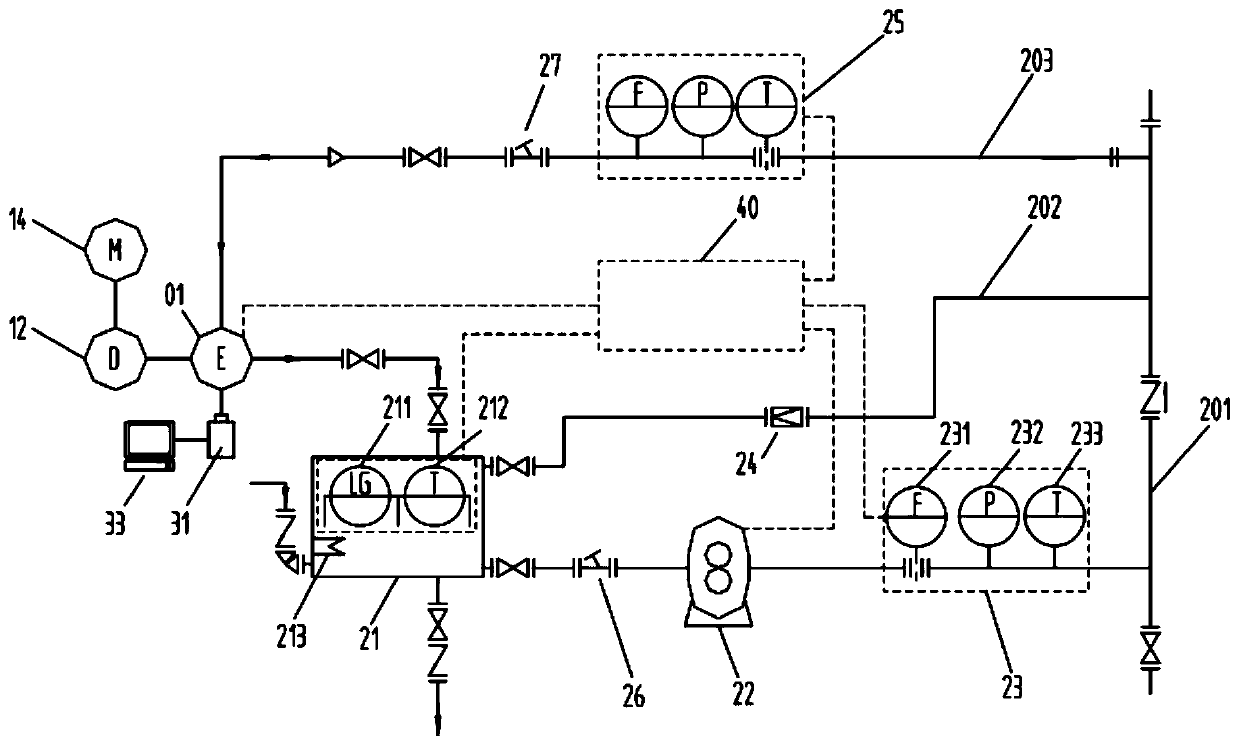
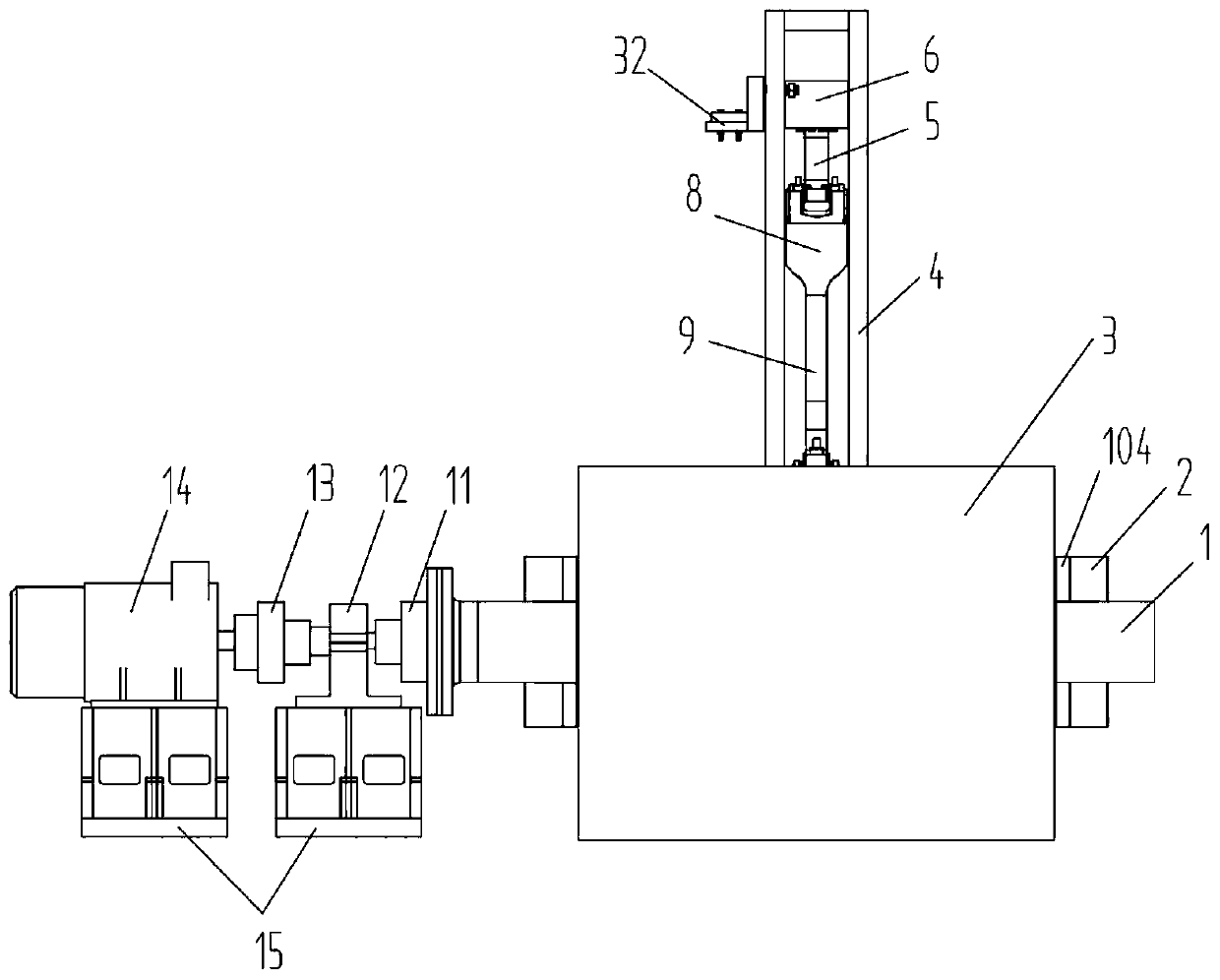
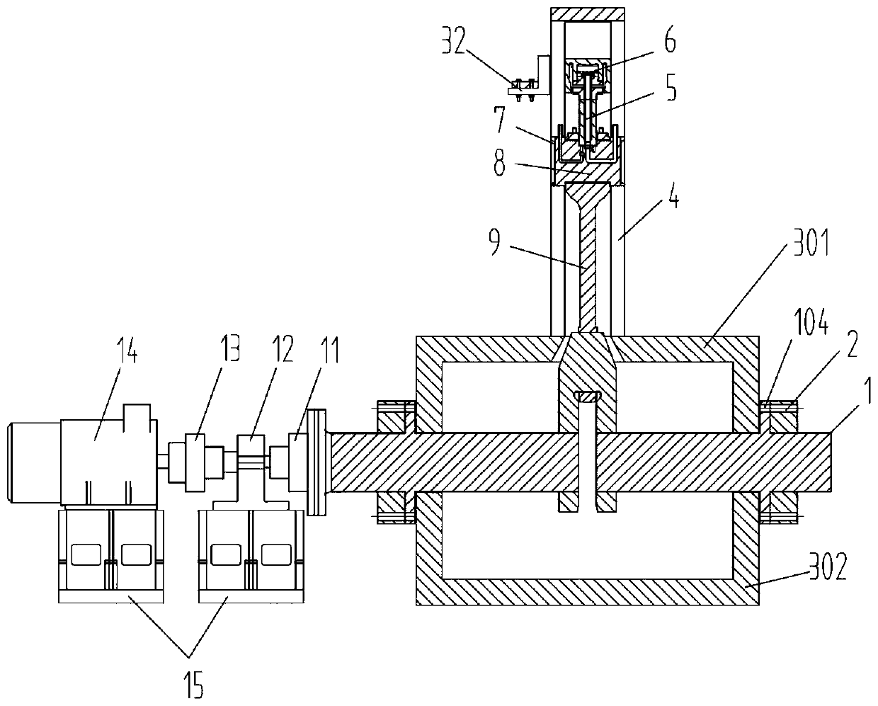
The invention aims at providing a visual simulation device for the oscillating flow in a cooling oil passage in a piston of a crosshead type diesel engine. The visual simulation device comprises a host model including a base, a crankshaft, a crosshead, a piston head and a guide rail. The base includes an upper base and a lower base. The crankshaft is installed between the upper base and the lowerbase through a hole channel. The guide rail is fixed on the upper base. The lower end of a connecting rod is connected with the crankshaft by a connecting rod journal of the crankshaft; and a crosshead is connected to the upper end of the connecting rod. Sliding blocks matching the guide rail are installed at the two sides of the crosshead; a groove is formed in the top of the crosshead; the lowerend of the piston rod is installed in the rove; the upper end of the piston rod is connected with a piston head. A cooling oil inlet and a cooling oil outlet are arranged in each sliding block; and aflow-in channel and a flow-out channel are formed in the crosshead. According to the invention, the oscillating flow distribution state and the cooling oil filling condition of the fluid in the piston head can be shot continuously; and the movement state and fullness of the two-phase flows in the cooling cavity at different rotation speeds, different pressures, different flow rates and differentcooling oil temperatures can be recorded.
Description
technical field [0001] The invention relates to a test device, in particular to a diesel engine test device. Background technique [0002] The piston in the combustion chamber of a diesel engine is subjected to periodic mechanical loads and thermal loads. Excessive temperature of the piston head will cause damage to the strength of the piston, burning or sticking of the top of the piston. There is a cooling chamber in the internal structure of the piston, which can effectively take away most of the heat flow in the combustion chamber. Whether the design of the internal cooling chamber of the piston head is reasonable or not directly affects the reliability, economy and life of the diesel engine. [0003] For the development examples of the oscillating flow simulation test device: CN101509824A, CN101793607A, CN102032991A, CN103994881A, CN108007693A, etc. all disclose a kind of piston oscillation cooling test device, wherein the piston simulation model of CN101509824A and CN1...
Claims
Login to View More Application Information
Patent Timeline
 IPC IPC(8): G01M15/04
CPCG01M15/04
Inventor明平剑梁冰张文平张新玉柳贡民赵晓臣国杰曹贻鹏
OwnerHARBIN ENG UNIV