UUV near sea surface visible light image defogging method

A visible light and image technology, applied in the field of image processing, can solve problems such as edge distortion and image edge problems, and achieve good defogging effect, remove large-area halo phenomenon, and retain image edge features.

Active Publication Date: 2019-09-06
HARBIN ENG UNIV
View PDF3 Cites 6 Cited by
  • Summary
  • Abstract
  • Description
  • Claims
  • Application Information

AI Technical Summary

Problems solved by technology

However, the median filter cannot solve the edge problem of the image very well, and it is easy to cause edge distortion

Method used


Image

  • UUV near sea surface visible light image defogging method
  • UUV near sea surface visible light image defogging method
  • UUV near sea surface visible light image defogging method

Examples


Embodiment 1

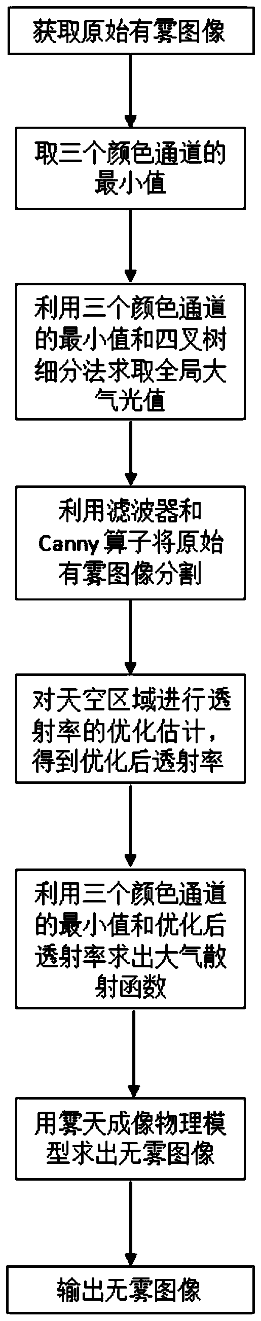
[0039] Such as figure 1 , A method for defogging visible light images on UUV offshore surface, including the following steps:

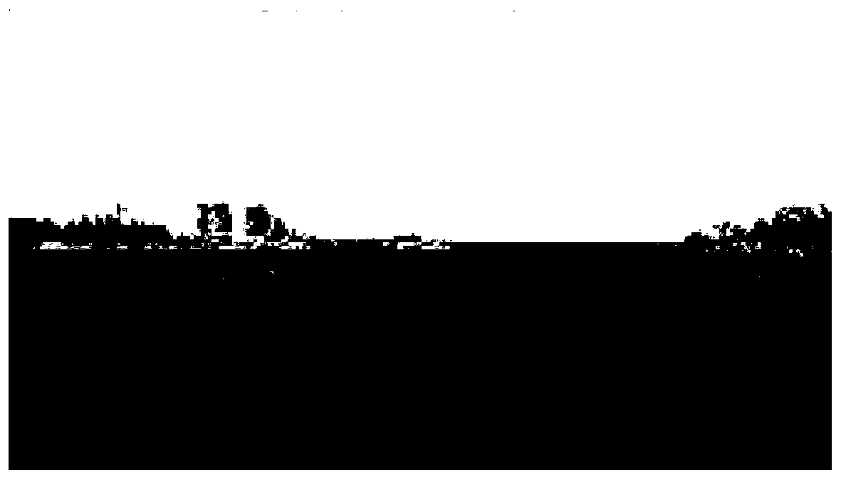
[0040] Step (1): Use VS2010 and OPENCV language to program input and display the original foggy image I(x), take the minimum of the three color channels for I(x) and mark it as M(x):

[0041] M(x)=min c∈{r,g,b} (I c (x));

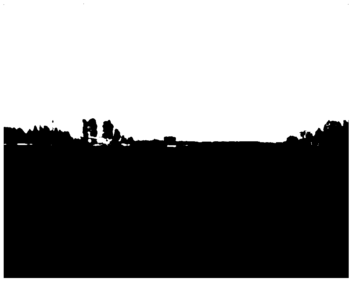
[0042] In the above formula, x is a pixel; the original foggy image is like figure 2 Shown. The image after taking the minimum of the three color channels is image 3 Shown.

[0043] Step (2): Use the minimum value M(x) of the three color channels and the quadtree subdivision method to obtain the global atmospheric light value A;

[0044] Step (2.1): Fit the divided sky area into a rectangle, then divide the sky area into four rectangular areas, and set the area threshold to S T ;

[0045] Step (2.2): Calculate the average value and variance of the pixels in each rectangular area, and take the average value minus the variance as the score...


PUM


Abstract

The invention belongs to the field of image processing, and discloses a UUV near sea surface visible light image defogging method, which comprises the following steps: step (1): obtaining an originalfoggy image, taking the minimum values of three color channels and recording the minimum values as M(x); step (2), solving a global atmospheric light value by using the minimum values of the three color channels and a quadtree subdivision method; step (3), dividing the original foggy image into a sky region and a non-sky region by using a filter and a Canny operator, and then carrying out transmittance optimization estimation on the sky region to obtain optimized transmissivity; and (4) solving an atmospheric scattering function by using the minimum values of the three color channels and the optimized transmissivity, and then solving a fog-free image by using a fog imaging physical model and outputting the fog-free image. According to the method, the problem of inaccurate transmissivity estimation caused by a large-range sky region and high-brightness regions such as water surface reflection and white wave flakes is solved, image edge characteristics can be reserved, a large-area lightring phenomenon can be removed, and the defogging effect is good.

Description

Technical field [0001] The invention belongs to the field of image processing, and in particular relates to a method for defogging visible light images on UUV offshore surfaces. Background technique [0002] China has a long coastline and the weather conditions at sea are very complicated. Ship collision accidents caused by sea fog are not uncommon. When light propagates in the atmospheric medium, it is refracted or reflected by suspended particles, causing a large number of features in the video image acquired by the image acquisition device installed on the maritime buoy or underwater vehicle to be masked, the contrast is reduced, and the edge details are blurred, which is easy to cause the image content Misjudgment will affect the subsequent target positioning, recognition and tracking. Therefore, the defogging processing of UUV near-sea visible light images is a practical and challenging problem. [0003] At present, various filtering techniques, such as joint bilateral filte...

Claims


Application Information

Patent Timeline
Patent Type & Authority Applications(China)
IPC IPC(8): G06T5/00G06T7/12G06T7/90
CPCG06T5/003G06T5/002G06T7/12G06T7/90G06T2207/20032Y02A90/10
Inventor 管凤旭尹健骅李娟严浙平杜雪
Owner HARBIN ENG UNIV
Why Eureka
Try Eureka