Electromagnet coil winding machine

An electromagnet coil and winding machine technology, applied in coil manufacturing, inductor/transformer/magnet manufacturing, circuits, etc., can solve the problem of disorderly winding, unable to achieve multi-layer precision winding, and unable to meet the space of individual coils requirements, etc.

Pending Publication Date: 2019-09-06
安阳凯地磁力科技股份有限公司
View PDF0 Cites 0 Cited by
  • Summary
  • Abstract
  • Description
  • Claims
  • Application Information

AI Technical Summary

Problems solved by technology

In the current technology, the principle of the electromagnet coil winding machine sold in the market is based on the combination of the spindle speed and the diameter of the enameled wire (the guide needle moves a wire diameter every time the spindle rotates, that is, the winding is forced, and the guide needle usually uses CNC screw slide mechanism), due to the influence of enameled wire diameter error, paint tumor, skeleton deformation, etc., it is inevitable that multi-layer precision winding cannot be realized. Practice has proved that when the number of layers exceeds 20 layers, the winding will inevitably occur. In the case of disorderly winding, especially the flat-bottomed skeleton cannot carry out multi-layer precision winding, so it cannot meet the space requirements of individual coils

Method used


Image

  • Electromagnet coil winding machine
  • Electromagnet coil winding machine
  • Electromagnet coil winding machine

Examples


Embodiment Construction

[0015] In order to more fully explain the implementation of the present invention, implementation examples of the present invention are provided. These implementation examples are only illustrations of the present invention, and do not limit the scope of the present invention.

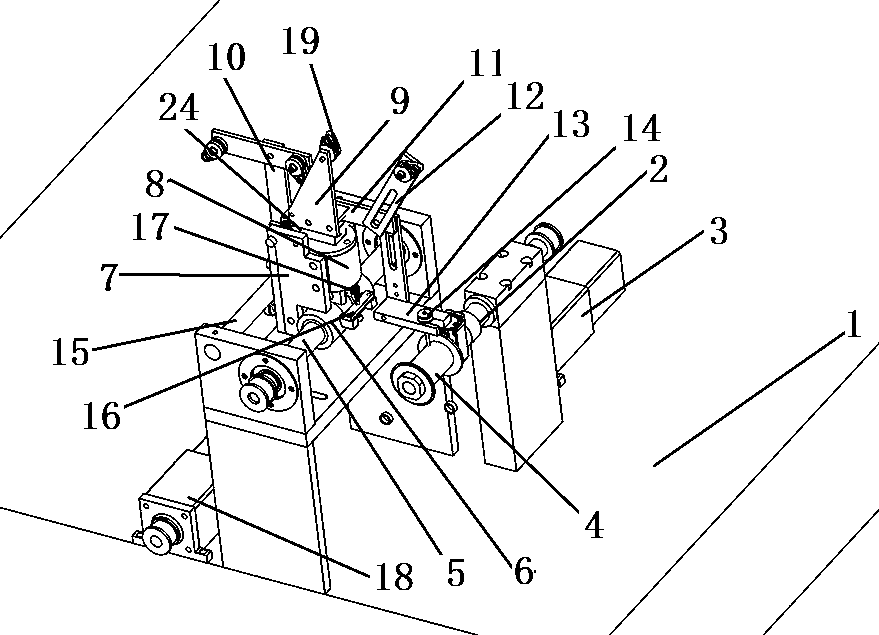
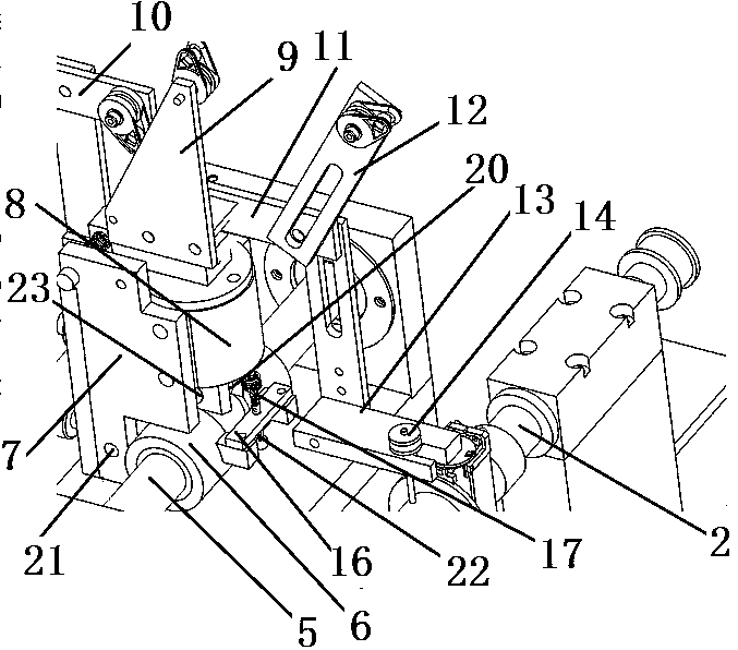
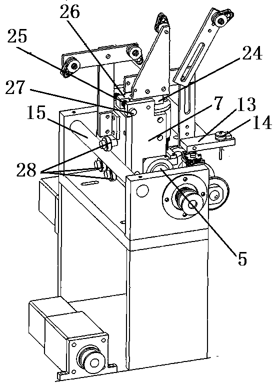
[0016] A further detailed explanation of the present invention is given in conjunction with the accompanying drawings. Each label in the accompanying drawings is: 1: frame; 2: main shaft; 3: main shaft motor; 4: bobbin; 5: optical axis; 6: sliding sleeve; 7: groove 8: Bearing sleeve; 9: Wire arm A; 10: Wire arm B; 11: Inverted L-shaped bracket; 12: Wire arm C; 13: Guide needle seat; 14: Hollow guide needle; 15: Positioning rod; 16 : Lower plate; 17: Adjusting spring; 18: Optical axis motor; 19: Anti-jumper; 20: Spherical bearing; 21: Pin hole B; 22: Adjusting bolt; 23: Spherical bearing shaft; 24: Connecting plate; 25 : balance positioning lug; 26: balance spring; 27: balance bolt; 28: guide wheel; 29...


PUM


Abstract

An electromagnet coil winding machine comprises a rack and a main shaft. The rack is rotatably provided with a smooth shaft. The smooth shaft is sleeved by a sliding sleeve. The upper portion of the sliding sleeve is provided with a window. Two ear portions at the back of the sliding sleeve are respectively provided with a pinhole A. The sliding sleeve is provided with a groove type member. The lower portion of the groove type member is provided with a pinhole B. A pin shaft passes through the pinhole A and the pinhole B. The groove type member is internally provided with a bearing sleeve. Thebearing sleeve is internally provided with a bearing. The bearing is internally provided with a vertical shaft. The lower end of the vertical shaft is provided with a spherical bearing. The upper endof the vertical shaft is connected with a connecting plate. The connecting plate is connected with a wire arm A. The back surface of the groove type member is connected with a T-shaped frame wire armB. The vertical edge of the T-shaped frame is connected with an inverted L-shaped support. The inverted L-shaped support is connected with a wire arm C. The end portion of each wire arm is provided with a wire jump preventer. A guide pin base is connected under the inverted L-shaped support. The guide pin base is provided with a hollow guide pin. The coil winding machine realizes ordered wire arrangement.

Description

technical field [0001] The invention relates to a winding machine, in particular to an electromagnetic coil winding machine, and belongs to the technical field of electromagnet production equipment. Background technique [0002] As the main key component in the field of hydraulic transmission, the solenoid core tube for valves is mainly used in automobiles, ships, aerospace, large and small machine tools, various engineering machinery, metallurgy and other industries, and its power coil winding production device has been widely studied , and its production mechanism is various. In the current technology, the principle of the electromagnet coil winding machine sold in the market is based on the combination of the spindle speed and the diameter of the enameled wire (the guide needle moves a wire diameter every time the spindle rotates, that is, the winding is forced, and the guide needle usually uses CNC screw slide mechanism), due to the influence of enameled wire diameter e...

Claims


Application Information

Patent Timeline
Patent Type & Authority Applications(China)
IPC IPC(8): H01F41/06H01F41/066
CPCH01F41/06H01F41/066
Inventor 孟凡朋崔朝卿张磊
Owner 安阳凯地磁力科技股份有限公司
Why Eureka
Try Eureka