Unmanned locomotive braking device

A braking device and unmanned driving technology, which is applied in the direction of braking transmission devices, brakes, braking components, etc., can solve problems such as poor braking effect, and achieve good braking effect, avoid shaking, and stable sliding

Pending Publication Date: 2019-09-10
HUNAN AUTOMOTIVE ENG VOCATIONAL COLLEGE
View PDF1 Cites 3 Cited by
  • Summary
  • Abstract
  • Description
  • Claims
  • Application Information

AI Technical Summary

Problems solved by technology

However, the first brake pad in this device is fixedly set, resulting in only the second brake pad for braking, and the braking effect is relatively poor

Method used


Image

  • Unmanned locomotive braking device
  • Unmanned locomotive braking device
  • Unmanned locomotive braking device

Examples


Embodiment 1

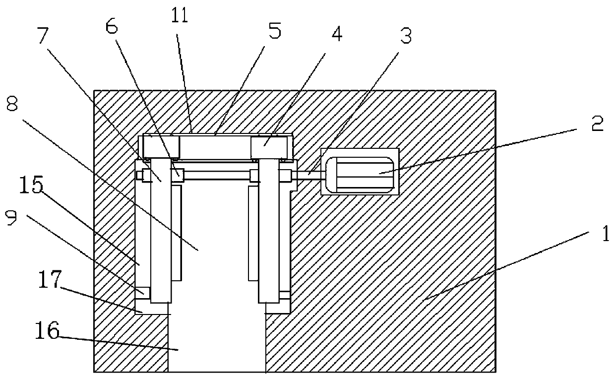
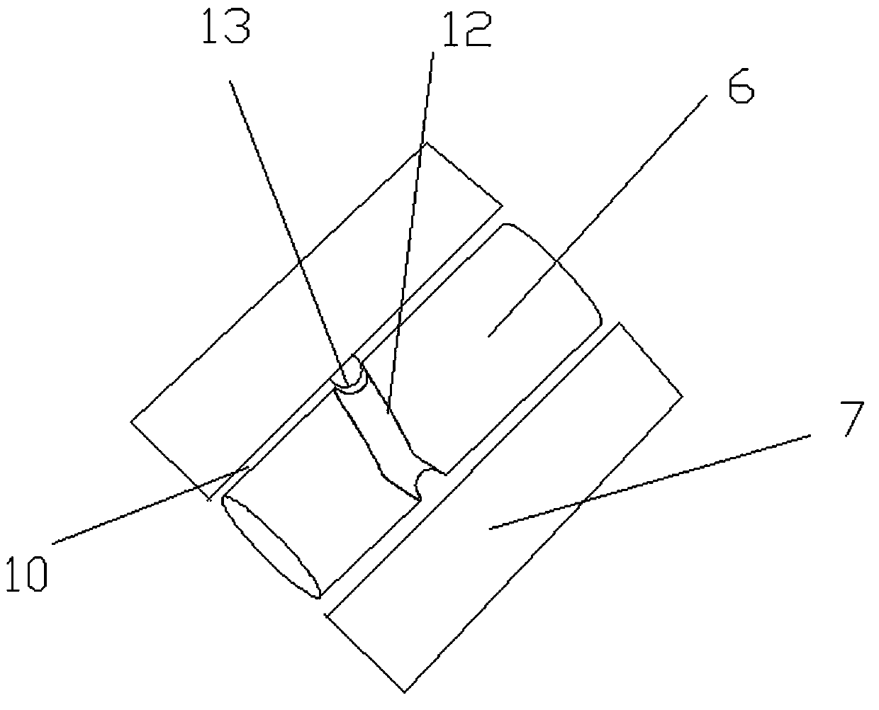
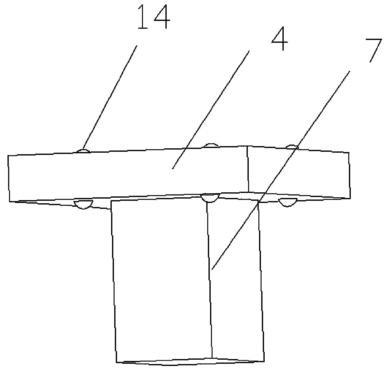
[0019] see Figure 1-3 , a braking device for an unmanned locomotive, comprising a device body 1 and a brake pad 7 . The inside of the device body 1 is provided with a brake chamber 8, and the top of the brake chamber 8 is provided with a sliding groove 5 inside the device body 1. Two sliding seats 4 are placed symmetrically at the left and right ends of the inside of the sliding groove 5. The sliding seats 4 can slide left and right inside the sliding groove 5. The upper and lower surfaces of the sliding seat 4 are rotatably provided with first balls 14, and the inside of the sliding groove 5 is provided with a first ball groove 11. The first balls 14 are nested in the inside of the first ball groove 11 and can slide. The setting of the first ball 14 makes the sliding of the sliding seat 4 smoother, avoiding that the sliding friction force of the sliding seat 4 is relatively large to cause poor sliding and wear the device. The setting of the first ball groove 11 makes the ...

Embodiment 2

[0023] On the basis of Embodiment 1, both sides of the brake chamber 8 are fixedly connected to the outer end of the horizontal guide rod 9 inside the device body 1, and the inner end of the guide rod 9 slides and nests in the bottom of the brake pad 7, and the guide rod 9 has a guiding effect on the brake pad 7, avoiding the shaking of the brake pad 7 during the sliding process, making the brake pad 7 slide more stably, and the braking effect is better.


PUM


Abstract

The invention relates to the technical field of brake devices, in particular to an unmanned locomotive braking device. The device comprises a device body and a brake pad, a brake cavity is formed in the device body; a horizontal sliding through hole is formed in the upper end of the brake pad; a second ball is rotationally arranged in the sliding through hole. A motor is fixedly mounted on the side edge of the brake cavity in the device body; an output shaft of the motor is coaxially and fixedly connected with a horizontal rotating shaft; and two rotating pieces are coaxially and fixedly connected to the rotating shaft, the rotating pieces are slidably embedded in the sliding through holes, two threaded second ball grooves are symmetrically formed in the side walls of the rotating pieces,the two second ball grooves are both 180 degrees in angle and are connected end to end, and second balls are embedded in the second ball grooves. The brake device has the advantages of simple structure, good brake effect, smooth sliding, good stability and convenience in popularization and implementation.

Description

technical field [0001] The invention relates to the technical field of braking devices, in particular to a braking device for an unmanned locomotive. Background technique [0002] Driverless car is a kind of smart car, also known as wheeled mobile robot. It mainly relies on the computer system-based smart driver in the car to achieve the goal of driverless driving. Enter the destination, and the car will automatically drive to the destination. The existing automatic braking device is mainly used as a supporting device for assisting the driver to drive safely, and can realize automatic braking when the vehicle runs into an emergency. [0003] Chinese patent (notification number: CN 208774753 U, announcement date: 2019.04.23) discloses a brake device for driverless cars, including a device body, the left end of the device body is fixed with a first brake pad, and the right end of the device body is rotatably connected There is a sliding plate, the lower end of the sliding pl...

Claims


Application Information

Patent Timeline
IPC IPC(8): B60T1/06B60T13/74
CPCB60T1/06B60T13/741
Inventor 程泊静谭慧胥刚陈标
Owner HUNAN AUTOMOTIVE ENG VOCATIONAL COLLEGE
Why Eureka
Try Eureka