Fixing structure for connectors

A technology for fixing structures and connectors, which is applied in the direction of connections, components of connecting devices, electrical components, etc., can solve the problems of difficult processing and unreliable positioning, and achieves low manufacturing difficulty, not easy to sway, and reliable positioning. Effect

Pending Publication Date: 2019-09-10
CHINA AVIATION OPTICAL-ELECTRICAL TECH CO LTD
View PDF1 Cites 0 Cited by
  • Summary
  • Abstract
  • Description
  • Claims
  • Application Information

AI Technical Summary

Problems solved by technology

[0005] The purpose of the present invention is to provide a connector fixing structure to solve the problems of difficult processing or unreliable positioning existing in the positioning structure on the existing connector

Method used


Image

  • Fixing structure for connectors
  • Fixing structure for connectors
  • Fixing structure for connectors

Examples


Embodiment 2

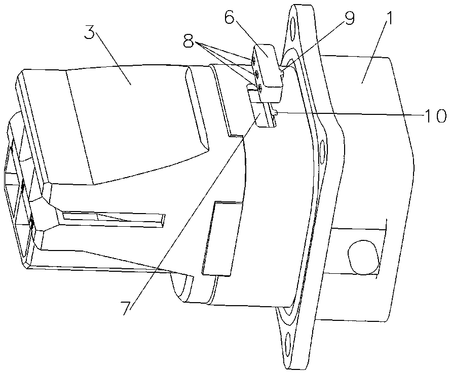
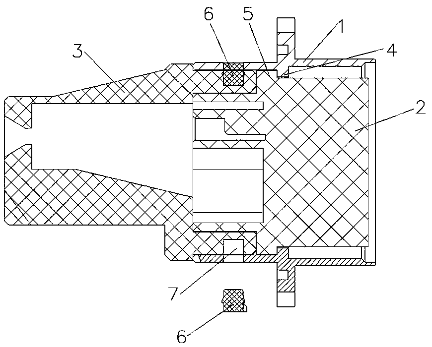
[0030] Embodiment 2, the difference between embodiment 2 and embodiment 1 is that the connector fixing structure can also be used to fix other components on the connector; for example, it is used to fix the insulator and the contact piece, and the contact piece is provided with a positioning The slot where the block is inserted, and the insulator is provided with a through groove for the positioning block to enter; when assembling, firstly put the contact piece into the insulator, and then install the positioning block into the connector housing as a whole.

Embodiment 3

[0031] The third embodiment, the difference between the third embodiment and the first embodiment is that the connector fixing structure can also be used on the circular connector; for example, the positioning groove is an arc-shaped groove, and the positioning block is an arc-shaped block.

Embodiment 4

[0032] Embodiment 4, the difference between embodiment 4 and embodiment 1 is that the positioning block can also use other structures to prevent it from coming off; for example, 1. The positioning block is pressed into the positioning groove by means of forced installation, and there is no need to set positioning protrusions 2. Glue the positioning block to the positioning groove.


PUM


Abstract

The invention relates to a fixing structure for connectors, which comprises a first component and a second component. The first component and the second component have a radial projection overlappingpart. The overlapping part of the first component and the overlapping part of the second component are provided with positioning slots corresponding to each other in position. Positioning members matching the positioning slots and used for axially stopping the first component and the second component at the same time are installed in the positioning slots. When the positioning members are installed, the positioning members are assembled into the positioning slots along the radial direction of a connector. The radial distance between the first component and the second component does not affectthe installation of the positioning members, and the radial distance between the two components can be set to be very small. The connector axially stops the first component and the second component. Compared with the prior art, the first component and the second component can be positioned reliably and are less prone to deflection, and the fixing structure is simple and less difficult to manufacture.

Description

technical field [0001] The invention relates to the field of connectors, in particular to a fixing structure for realizing fixed connection between components of the connector. Background technique [0002] Most connectors are composed of multiple parts, including contacts, plastics and housings, etc. The commonly used assembly and fixing structures between the parts include snap rings, retaining rings and rectangular connections on circular connectors. The claws and barbs on the weapon. [0003] The Chinese utility model patent with the notification number CN204067684U and the announcement date of 2014.12.31 discloses a connector fixing structure with elastic claws for positioning, including a housing, a front insulator and a rear insulator, and the front insulator is pressed on the shell by the rear insulator On the inner step of the body, the front end of the rear insulator is provided with elastic claws, and the shell is provided with a ring groove for the elastic claws...

Claims


Application Information

Patent Timeline
Patent Type & Authority Applications(China)
IPC IPC(8): H01R13/629H01R13/639
CPCH01R13/629H01R13/639
Inventor 乔珍珍张春建吴志富
Owner CHINA AVIATION OPTICAL-ELECTRICAL TECH CO LTD
Why Eureka
Try Eureka