
Rotor assembly, motor and vehicle

A rotor and component technology, applied in the direction of electric components, magnetic circuit rotating parts, electrical components, etc., can solve the problems of easy loosening of rotor core components, and achieve the effect of easy loosening and firm positioning

Pending Publication Date: 2019-09-10
GREE ELECTRIC APPLIANCES INC OF ZHUHAI
View PDF0 Cites 0 Cited by
  • Summary
  • Abstract
  • Description
  • Claims
  • Application Information

AI Technical Summary

Problems solved by technology

[0005] The main purpose of the present invention is to provide a rotor assembly, a motor and a vehicle to solve the technical problem that the rotor core assembly in the prior art tends to loosen during operation

Method used


Image

  • Rotor assembly, motor and vehicle
  • Rotor assembly, motor and vehicle
  • Rotor assembly, motor and vehicle

Examples


Embodiment Construction

[0031] It should be noted that, in the case of no conflict, the embodiments in the present application and the features in the embodiments can be combined with each other. The present invention will be described in detail below with reference to the accompanying drawings and examples.

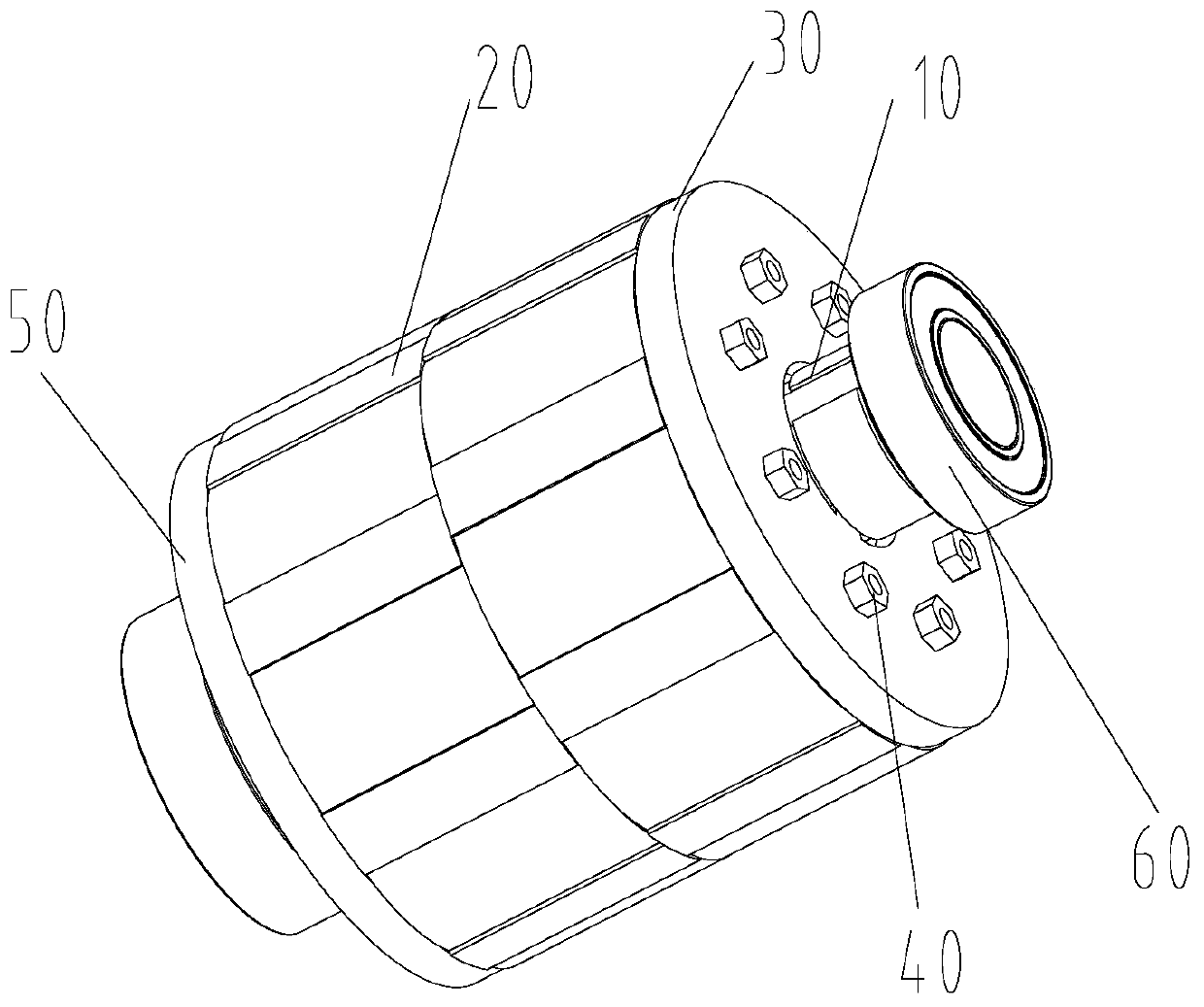
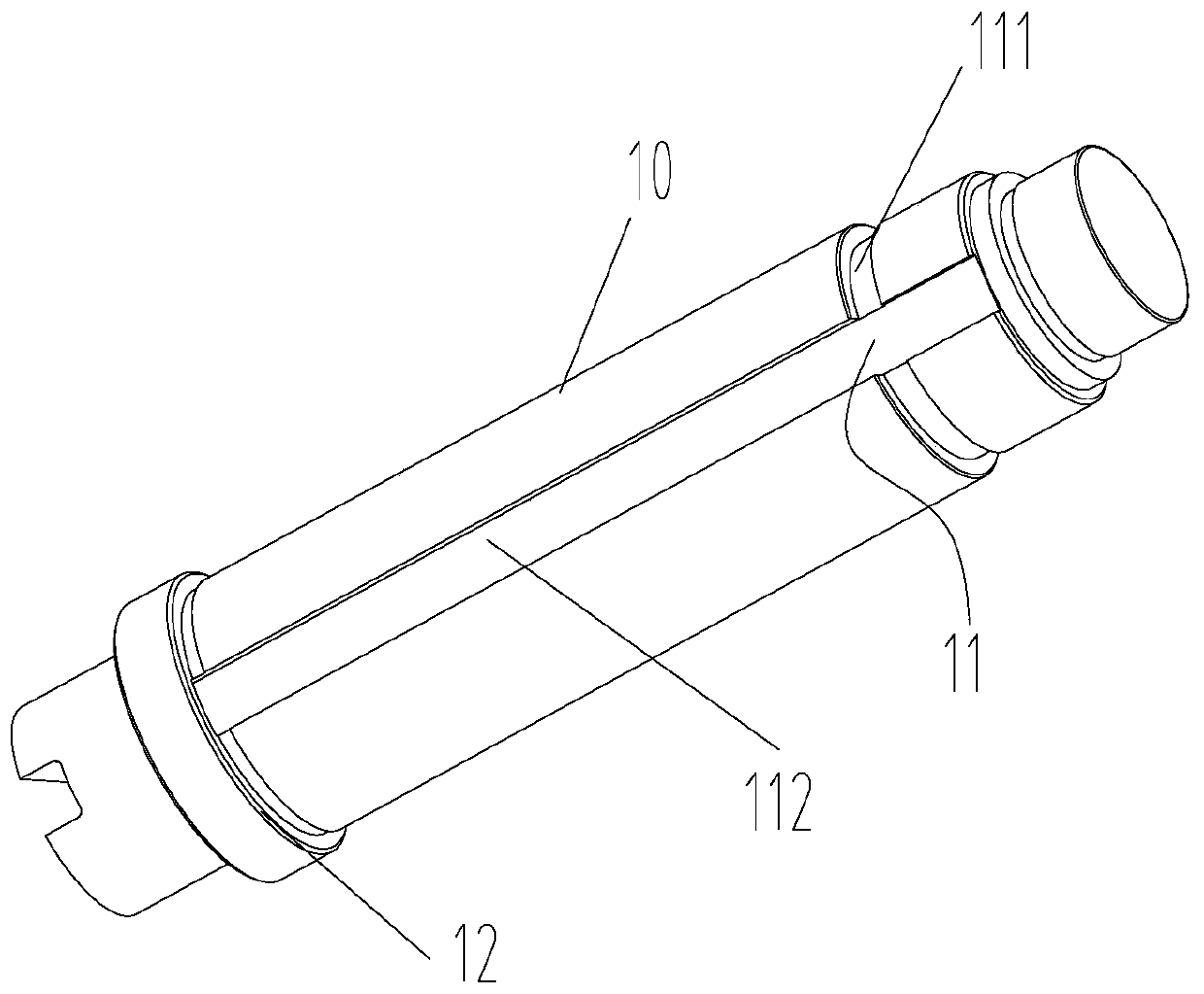
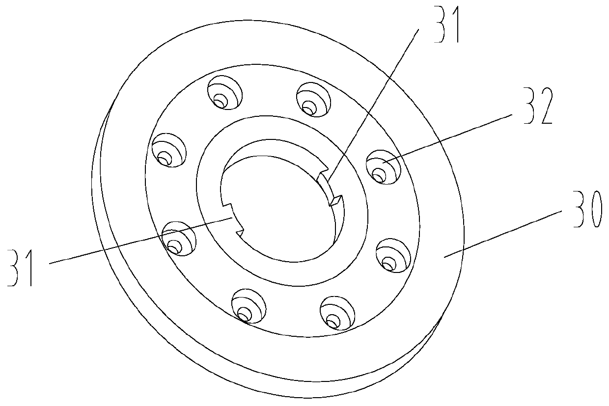
[0032] like Figure 1 to Figure 4 As mentioned above, Embodiment 1 of the present invention provides a rotor assembly, which includes: a rotor shaft 10 , a rotor core assembly 20 and a first rotor baffle 30 . One end of the rotor shaft 10 is provided with a positioning boss 12 , and the rotor core assembly 20 is sheathed on the rotor shaft 10 . The first rotor baffle 30 is sheathed on the rotor shaft 10 , and the rotor core assembly 20 is sandwiched between the positioning boss 12 and the first rotor baffle 30 . Wherein, the rotor shaft 10 is provided with a first positioning portion 11 , the first rotor baffle 30 is provided with a second positioning portion 31 matching with the first positi...


PUM


Abstract

The present invention provides a rotor assembly, a motor and a vehicle, the rotor assembly comprises: a rotor shaft, one end of which is provided with a positioning boss; a rotor core assembly, sleeved on the rotor shaft; a first rotor baffle, wherein the first rotor baffle is sleeved on the rotor shaft, and the rotor core assembly is disposed between a positioning convex platform and the first rotor baffle; wherein the rotor shaft is provided with a first positioning portion, and the first rotor baffle is provided with a second positioning portion that cooperates with the first positioning portion, the first positioning portion abuts the second positioning portion to enable the rotor shaft to perform axial positioning to the first rotor baffle. The technical solution can solve the technical problem that the rotor core assembly of the prior art is easy to loosening during operation.

Description

technical field [0001] The invention relates to the technical field of motors, in particular, to a rotor assembly, a motor and a vehicle. Background technique [0002] At present, with the continuous development of the automobile industry, the attention to energy and the demand for new energy vehicles are also becoming stronger. Under the changing trend of electrification, intelligence, light weight and sharing, it is particularly important to improve the performance of automobile motors. In the prior art, power steering is generally used to reduce the strength of turning the steering wheel, reduce driver fatigue, and improve driving safety. Power steering is to assist the driver to adjust the direction of the car. The difference between electro-hydraulic power assist and mechanical power assist is that motor drive replaces engine drive. With the gradual development of new energy sources, motor drive will replace the engine and become the core component of the car. [000...

Claims


Application Information

Patent Timeline
IPC IPC(8): H02K1/22H02K7/00
CPCH02K1/22H02K7/003
Inventor 董垚谭福慧杨晓琴高尤坤唐志伟张静
Owner GREE ELECTRIC APPLIANCES INC OF ZHUHAI
Features
  • Generate Ideas
  • Intellectual Property
  • Life Sciences
  • Materials
  • Tech Scout
  • Unparalleled Data Quality
  • Higher Quality Content
  • 60% Fewer Hallucinations
Learn More