
Water surface photovoltaic power generation device

A photovoltaic power generation and photovoltaic panel technology, which is applied in the field of water surface photovoltaic power generation devices, can solve problems such as increasing cost, limited buffering effect, and increasing maintenance work, and achieves the effects of improving shock absorption, strong practicability, and prolonging service life.

Inactive Publication Date: 2019-09-10
DONGGUAN UNIV OF TECH
View PDF6 Cites 7 Cited by
  • Summary
  • Abstract
  • Description
  • Claims
  • Application Information

AI Technical Summary

Problems solved by technology

[0002] With the strengthening of the international energy crisis and environmental protection awareness, solar photovoltaic power generation has been widely promoted. Due to the large area required for solar photovoltaic power generation, it often occupies a large amount of land area, and the available land area is very limited. Floating photovoltaic power plants on water use supporting floating bodies to float photovoltaic modules on the water surface to generate electricity. The feature is that the cooling effect of water on photovoltaic modules without occupying land resources can increase power generation. Evaporation, inhibition of algae reproduction, and protection of water resources, but the existing floating photovoltaic power generation is mostly intensive, and the solar panels are under the action of wind and waves, and the buoys appear wavy, causing collisions between solar panels and causing damage. Affect power generation, increase maintenance work, increase costs, etc.
[0003] The Chinese patent authorization announcement number is CN 208890727 U, which discloses a floating photovoltaic power generation device on the water surface, which can protect the solar panel, prevent damage caused by collision with the solar panel, does not affect the normal power generation, reduces maintenance work, and reduces costs , although this device can play a certain buffering effect, it only uses the buffer spring for buffering, the buffering effect is limited, and it is easy to damage

Method used


Image

  • Water surface photovoltaic power generation device
  • Water surface photovoltaic power generation device
  • Water surface photovoltaic power generation device

Examples


Embodiment 1

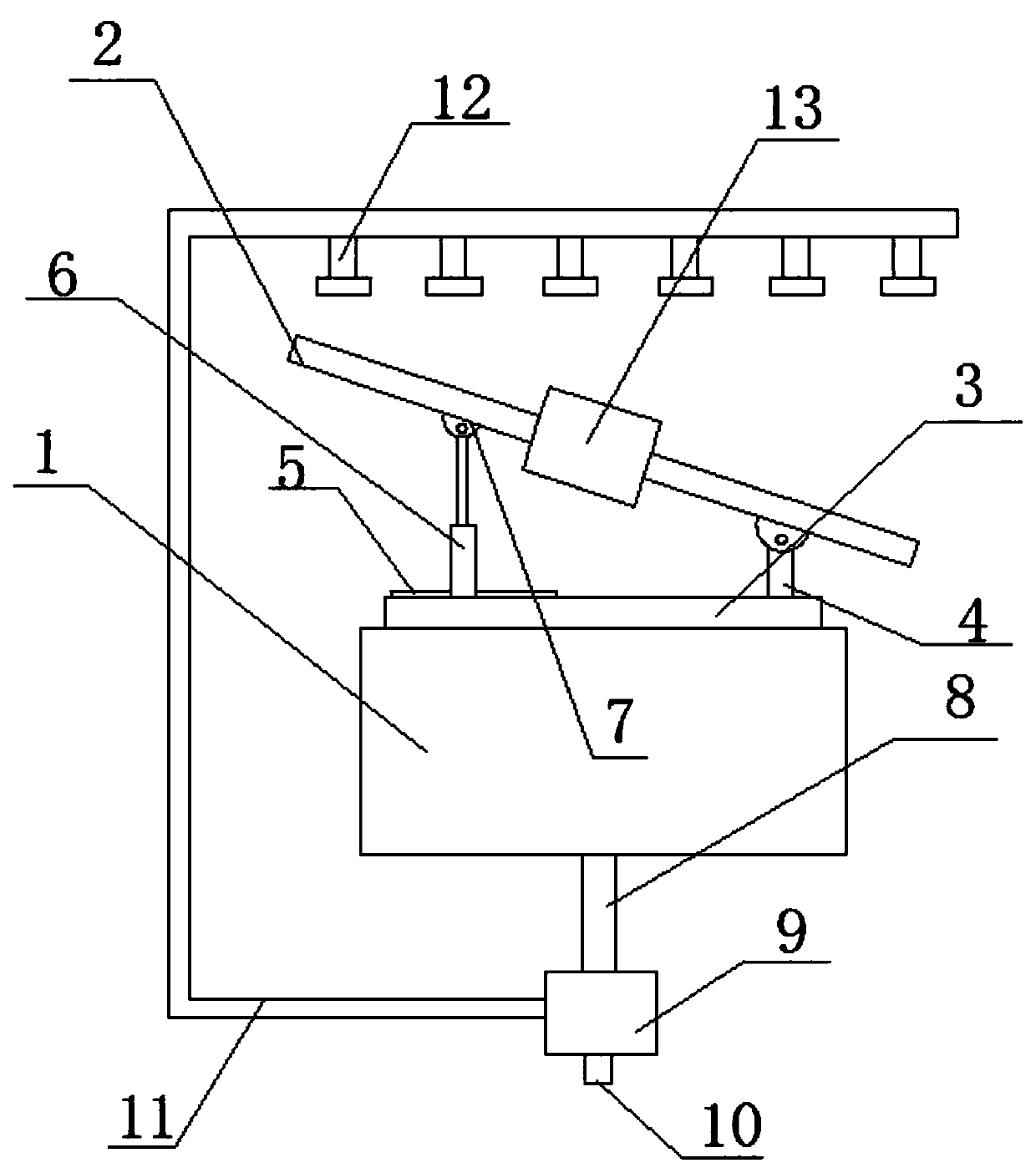
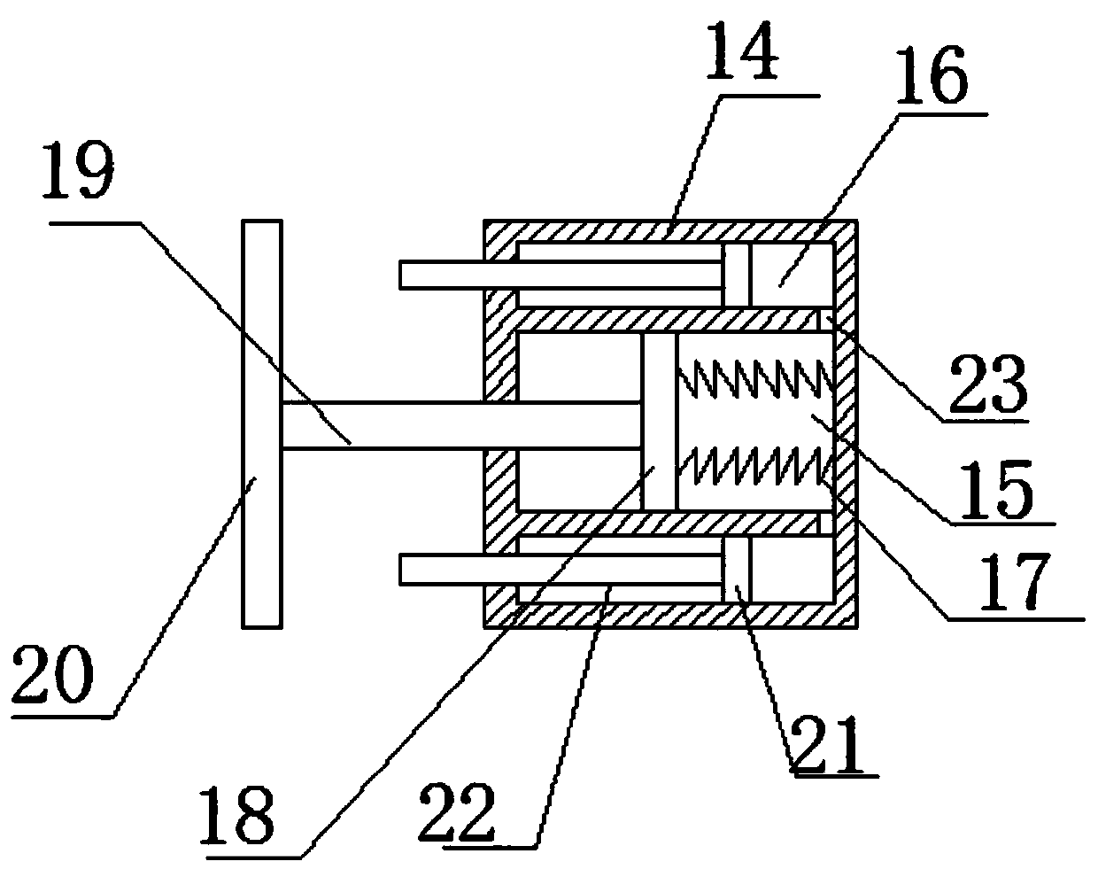
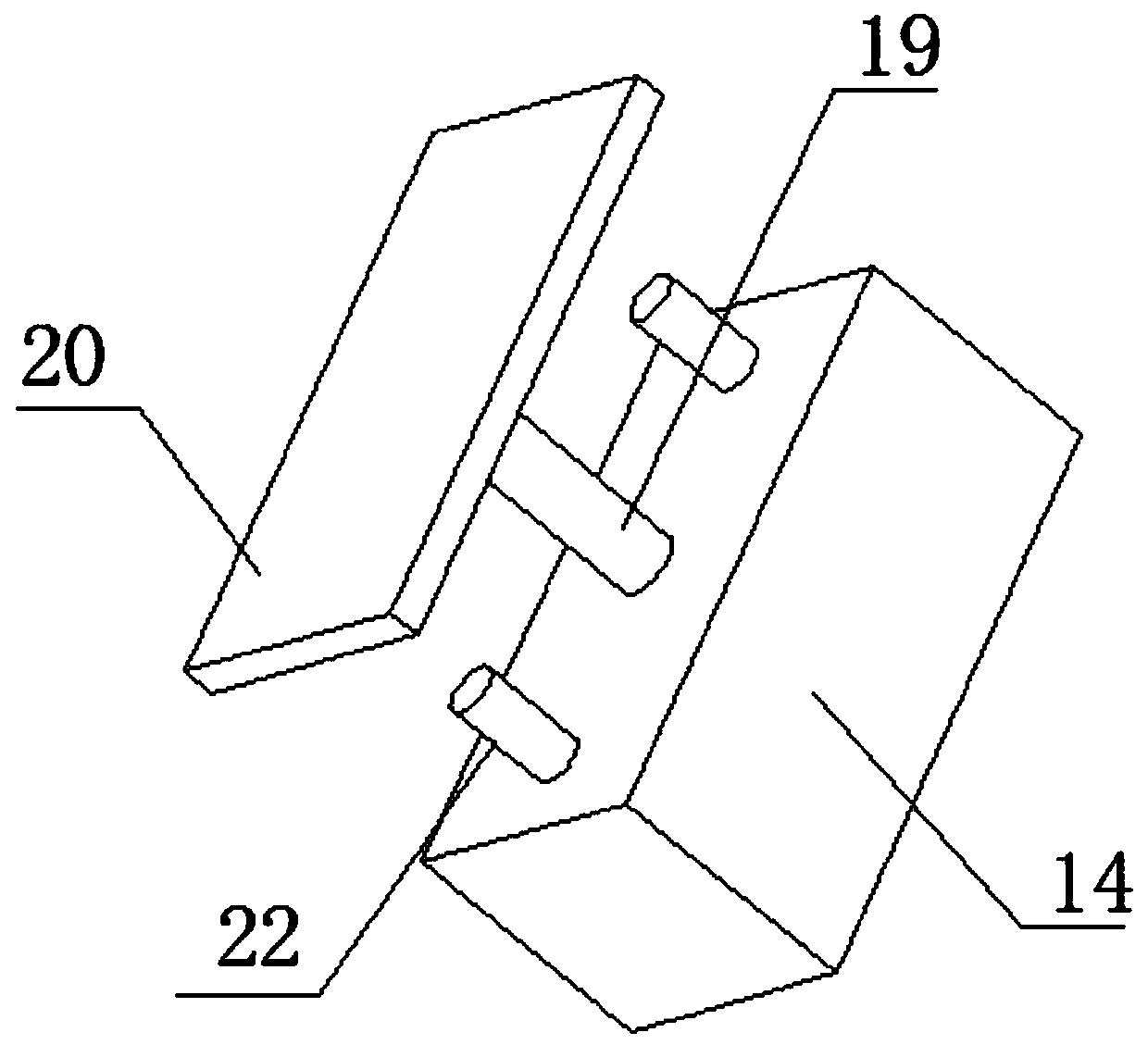
[0024] refer to Figure 1-4 , a water surface photovoltaic power generation device in the embodiment of the present invention includes a buoyancy base 1, a motor cavity 24 is opened in the middle of the upper side of the buoyancy base 1, and a motor 28 is installed inside the motor cavity 24, and the motor 28 The output end is provided with a rotating plate 3, the upper side of the rotating plate 3 is equipped with a photovoltaic panel 2 through a supporting mechanism, and the outer side of the photovoltaic panel 2 is provided with a buffer mechanism 13, and the buffer mechanism 13 includes a buffer seat 14. A first buffer chamber 15 is provided in the middle of the interior of the buffer seat 14, and a second buffer chamber 16 is provided symmetrically on both sides of the first buffer chamber 15, and a buffer spring 17 is arranged inside the first buffer chamber 15, so that The outer end of the buffer spring 17 is connected with a first piston plate 18, and the outer side of...

Embodiment 2

[0027] On the basis of Embodiment 1, a bracket 25 is provided inside the motor cavity 24, the motor 28 is mounted on the bracket 25, and a number of drain pipes 26 arranged obliquely are opened outside the motor cavity 24. The outer end of the pipe 26 communicates with the outside of the buoyancy seat 1 , and the inside of the drain pipe 26 is provided with a one-way valve 27 . The setting of this structure can make the motor 28 far away from the bottom of the motor chamber 24. When the motor chamber is flooded, the motor 28 can be prevented from being soaked, and the water can be discharged through the drain pipe 26. The setting of the one-way valve 27 can prevent water from being soaked. Enter the motor cavity from the drain pipe 26.

Embodiment 3

[0029] A counterweight bar 8 is installed in the middle of the lower end of the buoyancy base 1, a water pump 9 is installed at the lower end of the counterweight bar 8, a water suction pipe 10 is installed at the lower end of the water pump 9, and a water spray pipe is installed on the water pump 9 11. The other end of the water spray pipe 11 is located above the photovoltaic panel 2 and several cleaning spray heads 12 are provided. The setting of this structure can not only clean the photovoltaic panel 2, but also improve the stability of the buoyancy base 1, preventing the device from falling due to impact, and has strong practicability.


PUM


Abstract

The invention relates to the technical field of photovoltaic power generation, in particular to a water surface photovoltaic power generation device. The water surface photovoltaic power generation device comprises a buoyancy seat; a buffer mechanism comprises a buffer seat, wherein a first buffer cavity is formed in the middle of the inner part of the buffer seat; second buffer cavities are symmetrically formed in the two sides of the first buffer cavity, and a buffer spring is arranged in the first buffer cavity; the outer end of the buffer spring is connected with a first piston plate, anda support column is arranged on the outer side of the first piston plate; the outer end of the support column extends out of the buffer seat and is connected with a buffer plate; the first buffer cavity and the second buffer cavities are communicated through a pipeline; a second piston plate is arranged in the second buffer cavity; a rubber damping rod is arranged on the outer side of the second piston plate; and the outer end of the rubber damping rod extends out of the buffer seat. According to the device, the buffer mechanism is arranged, so that the damping effect is improved, the buffer spring can be protected, the service life of the device is prolonged, and the practicability is high.

Description

technical field [0001] The invention relates to the technical field of photovoltaic power generation, in particular to a water surface photovoltaic power generation device. Background technique [0002] With the strengthening of the international energy crisis and environmental protection awareness, solar photovoltaic power generation has been widely promoted. Due to the large area required for solar photovoltaic power generation, it often occupies a large amount of land area, and the available land area is very limited. Floating photovoltaic power plants on water use supporting floating bodies to float photovoltaic modules on the water surface to generate electricity. The feature is that the cooling effect of water on photovoltaic modules without occupying land resources can increase power generation. Evaporation, inhibition of algae reproduction, and protection of water resources, but the existing floating photovoltaic power generation is mostly intensive, and the solar pa...

Claims


Application Information

Patent Timeline
Patent Type & Authority Applications(China)
IPC IPC(8): H02S20/32F24S30/425F24S20/70H02S40/10F16F9/02F16F9/32
CPCF16F9/0281F16F9/3207F24S20/70F24S30/425H02S20/32H02S40/10Y02E10/47Y02E10/50
Inventor 陈平平张志坚杨雷
Owner DONGGUAN UNIV OF TECH
Learn More