A vibration damping device for a capacitor processing machine tool

A capacitor processing and vibration damping device technology is applied in metal processing mechanical parts, metal processing equipment, manufacturing tools, etc. The effect of flexibility, reduced amplitude and stable equipment

Active Publication Date: 2021-12-17
南通南塔电容器有限责任公司
View PDF6 Cites 0 Cited by
  • Summary
  • Abstract
  • Description
  • Claims
  • Application Information

AI Technical Summary

Problems solved by technology

[0004] In order to solve the above-mentioned technical problems, the present invention provides a vibration damping device for a capacitor processing machine tool, to solve the problem that the existing vibration damping device of a capacitor processing machine tool has too much friction and relatively large noise, and cannot automatically offset the vibration. Unable to reduce its own amplitude, unable to adjust the damping strength according to the machine tool specifications, and unable to cushion the inertial force of the equipment

Method used


Image

  • A vibration damping device for a capacitor processing machine tool
  • A vibration damping device for a capacitor processing machine tool
  • A vibration damping device for a capacitor processing machine tool

Examples


Embodiment 1

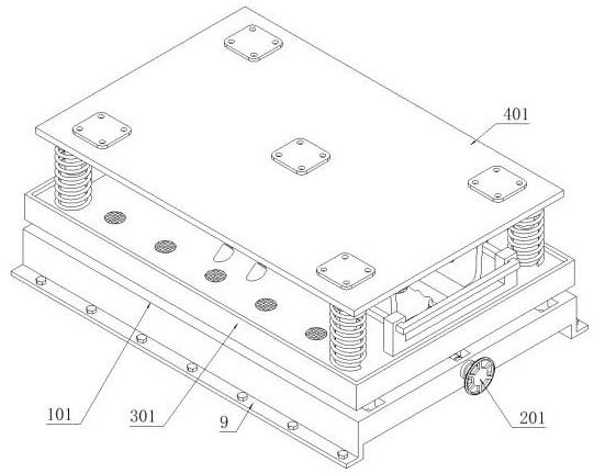
[0081] as attached figure 1 to attach Figure 17 Shown:

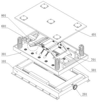
[0082] The invention provides a vibration damping device for a capacitor processing machine tool, which includes a support device 1; a support device 1, and mounting plates 9 are fixedly connected to both sides of the support device 1; A collection connection part 3 is installed, and a machine tool installation part 4 is fixedly connected to the collection connection part 3; a driving support part 6 is installed on the top of the machine tool installation part 4; two pressurizing devices 7 are fixedly connected to the top of the collection connection part 3, and the two The structures on the two pressurizing devices 7 are the same; two lubricating and cooling parts 8 are installed on the collecting connection part 3, and the structures on the two lubricating and cooling parts 8 are the same; The screw rod 201 is rotated and connected to the support base 101; and the opposite screw rod 201 is provided with a reverse th...

Embodiment 2

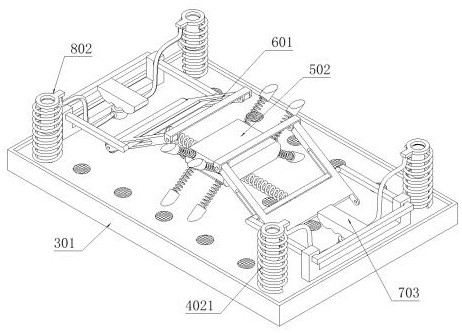
[0086] as attached Figure 12 , 13As shown, the stabilizing device 5 includes: tightening extension springs 501, eight tightening extension springs 501 are provided; four tightening extension springs 501 on the upper side are fixedly connected to the bottom of the machine tool mounting plate 401, and four tightening extension springs on the lower side 501 is fixedly connected on the collection box 301; counterweight 502, and counterweight 502 is fixedly connected on eight tension springs 501; the driving support part 6 comprises: driving bracket 601, and driving bracket 601 is provided with two; The drive bracket 601 is connected to the bottom of the machine tool mounting plate 401 through the bracket rotation; the middle part supports the extension spring 602, and the middle part supports the extension spring 602 and is fixedly connected between the two drive brackets 601; the drive support part 6 also includes: a roller 603, the roller 603 is provided with Two, two rollers ...

Embodiment 3

[0088] On the basis of the first embodiment, other structures remain unchanged. This embodiment provides another structural form of the pressure applying block 703, which can solve the problem that the long-term use of the pressure applying block 703 causes greater wear and tear on the pressurizing pump head 801. The device 7 includes: a pressurized driving frame 701, which is slidably connected to the linkage groove 604; a sliding bracket 702, which is fixedly connected to the collection box 301, and the sliding bracket 702 is slidably connected to a pressurized driving frame 701; the pressing block 703, the pressing block 703 is fixedly connected on the pressurizing drive frame 701; the wear-resistant rubber pad is fixedly connected at the bottom of the pressing block 703, which can effectively reduce the pressure applying block 703 on the pressurizing pump head 801 Wear and tear, better protect the pressurized pump head 801; two drive brackets 601 drive the pressurized drive...


PUM


Abstract

The invention provides a vibration damping device for a capacitor processing machine tool, which relates to the technical field of machine tool vibration reduction, and solves the problem that the existing vibration damping device of a capacitor processing machine tool has too much friction force of the damping part, and there is a large noise, which cannot reduce its own amplitude. Affecting the machining accuracy of machine tools, it is impossible to adjust the damping force according to the specifications of the machine tool, and it is impossible to cushion the inertial force of the equipment, including the support device; the support device has mounting plates fixedly connected to both sides of the support device; The cushioning adjustment part; the collection connection part is installed on the top of the support device, and the machine tool installation part is fixedly connected to the collection connection part; the drive support part is installed on the top of the machine tool installation part; The kinetic energy of its own shock absorption can automatically realize the supply of lubricating oil, which can not only keep the lubrication of the shock absorbing parts, but also save lubricating oil, and effectively improve the service life of the equipment as a whole.

Description

technical field [0001] The invention belongs to the technical field of vibration reduction of machine tools, and more specifically relates to a vibration reduction device of a capacitor processing machine tool. Background technique [0002] Two conductors that are close to each other sandwich a layer of non-conductive insulating medium, which constitutes a capacitor. A machine tool refers to a machine that manufactures a machine, also known as a machine tool or a machine tool. It is customarily referred to as a machine tool. The production and processing process of large capacitors In the process, the machine tool itself will have a large vibration, and at this time, the vibration damping device of the capacitor processing machine tool will be used. [0003] Based on the findings of the existing technology, the vibration damping device of the existing capacitor processing machine tool is not equipped with a vibration linkage lubrication device, and the friction force of the ...

Claims


Application Information

Patent Timeline
Patent Type & Authority Patents(China)
IPC IPC(8): B23Q11/00B23Q11/12
CPCB23Q11/0032B23Q11/0035B23Q11/121
Inventor 邹万青
Owner 南通南塔电容器有限责任公司
Why Eureka
Try Eureka