Supercharge Your Innovation With Domain-Expert AI Agents!

A debugging device for binocular camera that can be accurately adjusted and corrected by infrared operation

A binocular camera, infrared technology, applied in the direction of television, electrical components, image communication, etc., can solve the problem of not many devices for adjusting posture, and achieve the effect of improving accuracy

Active Publication Date: 2021-03-05
深圳市华芯技研科技有限公司
View PDF6 Cites 0 Cited by
  • Summary
  • Abstract
  • Description
  • Claims
  • Application Information

AI Technical Summary

Problems solved by technology

The development of binocular vision technology increasingly requires more accurate and convenient adjustment devices to cooperate with it. At present, there are not many adjustment devices in this regard, and it is difficult to meet the requirements of object imaging and calibration.

Method used


Image

  • A debugging device for binocular camera that can be accurately adjusted and corrected by infrared operation
  • A debugging device for binocular camera that can be accurately adjusted and corrected by infrared operation
  • A debugging device for binocular camera that can be accurately adjusted and corrected by infrared operation

Examples


Embodiment Construction

[0020] The following will clearly and completely describe the technical solutions in the embodiments of the present invention with reference to the accompanying drawings in the embodiments of the present invention. Obviously, the described embodiments are only some, not all, embodiments of the present invention. Based on the embodiments of the present invention, all other embodiments obtained by persons of ordinary skill in the art without making creative efforts belong to the protection scope of the present invention.

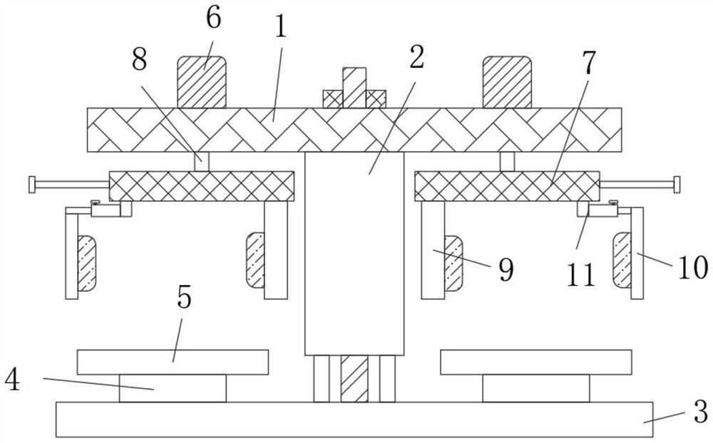
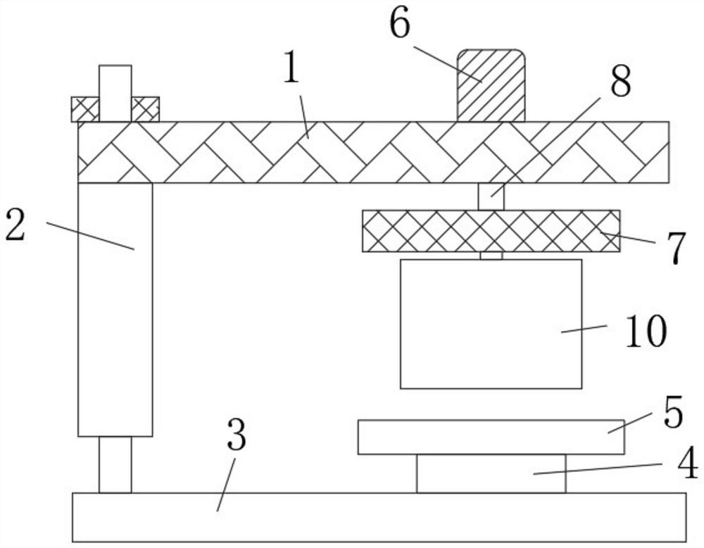
[0021] The present invention provides such Figure 1-5 A binocular camera as shown can be accurately adjusted and corrected by infrared operation, and the debugging device is composed of figure 1 with figure 2 As shown, including the top plate 1, the connection assembly 2 and the bottom plate 3, the top plate 1 The middle part of the bottom surface is connected with the middle part of the top surface of the bottom plate 3 through the connection assembly 2, ...


PUM


Abstract

The invention discloses a debugging device capable of accurately adjusting and correcting through infrared operation for a binocular camera, relating to the field of binocular cameras. The device comprises a top plate, connecting assemblies and a bottom plate. The middle of one end of the bottom face of the top plate is connected with the middle of one end of the top face of the bottom plate through a connecting assembly. Rotating discs are fixedly installed on the two sides of the other end of the top face of the bottom plate. Supporting plates are fixedly connected to the top ends of the rotating discs, and servo motors are fixedly connected to the two sides of the other end of the top face of the top plate. The connecting assembly is arranged between the top plate and the bottom plate,and the spacing rod on the connecting assembly is matched with the threaded lantern ring to adjust the distance between the top plate and the bottom plate, so that the device can be fixed on a bracketof the binocular camera. Aservo motor and a movable plate are arranged on the top plate. The servo motor can drive the movable plate to rotate to finely adjust the lens of the camera, and the infrared emitter is arranged on the movable plate, so that lens adjustment accuracy can be improved.

Description

technical field [0001] The invention relates to the field of binocular cameras, in particular to a debugging device for binocular cameras that can be precisely adjusted and corrected by infrared operation. Background technique [0002] Machine vision technology is more and more widely used in the current industry, and it is playing an increasingly important role in replacing human beings. Binocular vision is one of the technologies that uses two cameras to solve the problem of stereo vision, and is widely used in ranging, surface 3D reconstruction, reverse engineering and other fields. [0003] To establish a binocular vision system, camera position adjustment and camera calibration are required. Only when the two cameras have a good relative position can a common field of view with a large cross area be obtained, which is conducive to subsequent target point matching; the purpose of calibration is to obtain the internal and external parameters of the camera, and the intern...

Claims


Application Information

Patent Timeline
Patent Type & Authority Patents(China)
IPC IPC(8): H04N17/00
CPCH04N17/002
Inventor 姜珂于大明赵立军张海锋
Owner 深圳市华芯技研科技有限公司
Features
  • R&D
  • Intellectual Property
  • Life Sciences
  • Materials
  • Tech Scout
  • Unparalleled Data Quality
  • Higher Quality Content
  • 60% Fewer Hallucinations
Learn More