Eureka AIR delivers breakthrough ideas for toughest innovation challenges, trusted by R&D personnel around the world.

Installation structure for cabinet laminates and cabinet

A technology of installation structure and cabinet body, applied in the application, cabinet, thin plate connection and other directions, can solve the problem of inconvenient adjustment of opening and position, and achieve the effect of good contact effect, large anti-skid resistance and good load-bearing effect.

Inactive Publication Date: 2019-09-13
JOMOO KITCHEN & BATHROOM
View PDF7 Cites 0 Cited by
  • Summary
  • Abstract
  • Description
  • Claims
  • Application Information

AI Technical Summary

Problems solved by technology

[0003] The purpose of the present invention is to overcome the above-mentioned defects or problems in the background technology, and provide a kind of installation structure and cabinet for the cabinet laminate, which solves the problems of the current laminate installation structure and cabinet. Installation requires holes and the position is not easy to adjust

Method used


Image

  • Installation structure for cabinet laminates and cabinet
  • Installation structure for cabinet laminates and cabinet
  • Installation structure for cabinet laminates and cabinet

Examples


Embodiment Construction

[0035] The following will clearly and completely describe the technical solutions in the embodiments of the present invention with reference to the drawings in the embodiments of the present invention. Obviously, the described embodiments are preferred embodiments of the invention and should not be seen as excluding other embodiments. Based on the embodiments of the present invention, all other embodiments obtained by persons of ordinary skill in the art without creative efforts fall within the protection scope of the present invention.

[0036] In the claims, description and above-mentioned drawings of the present invention, unless otherwise clearly defined, the terms "first", "second" or "third" are used to distinguish different objects, not for Describe a specific order.

[0037] In the claims, specification and above-mentioned drawings of the present invention, unless otherwise clearly defined, for orientation words, such as using the terms "center", "transverse", "longit...


PUM


Abstract

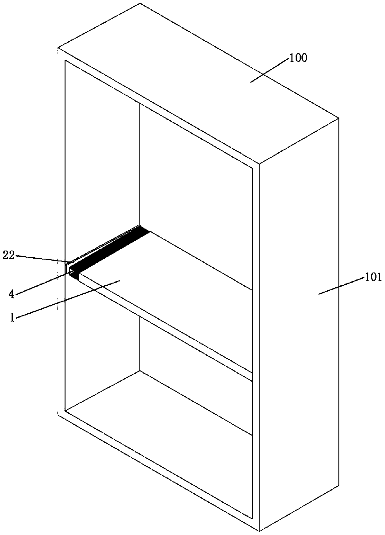
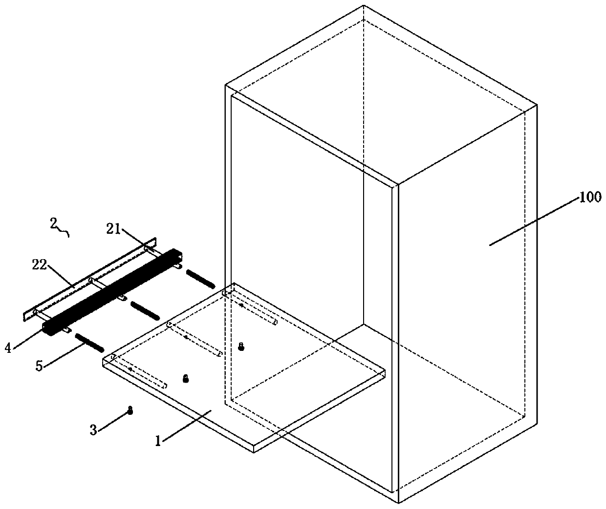
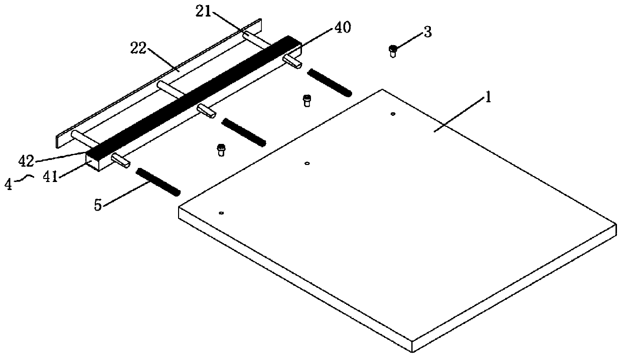
The invention discloses an installation structure for cabinet laminates and a cabinet. The installation structure used for cabinet laminates comprises laminates, and concave holes are formed in one side or two sides of the two side faces, assembled with a cabinet body side plate, of the laminates; an abutting assembly, wherein one end of the abutting assembly is arranged in the concave holes in asliding mode, the other end of the abutting assembly extends out to abut against the cabinet body side plate, and the side wall of the part, located in the concave holes, of the abutting assembly is provided with an inclined surface; and a pressing piece, wherein one end of the pressing piece extends into the concave holes and abuts against the inclined surface to form inclined surface matching relation, and the inclined surface matching relation is configured to push the abutting assembly to slide towards one side outside the concave holes and abut against the cabinet body side plate when thelocking depth of the pressing piece is increased. The laminates in the cabinet body are fixedly arranged between the side plates on the two sides of the cabinet body through the installation structure for cabinet laminates. According to the installation structure for cabinet laminates and the cabinet, the problems that holes need to be formed in existing laminate installation and the position isinconvenient to adjust are solved.

Description

technical field [0001] The invention relates to the technical field of furniture products, in particular to an installation structure for cabinet laminates and a cabinet. Background technique [0002] The laminates in the existing cabinets need to be installed by opening holes in the side panels of the cabinet and using laminate brackets. The positions of the holes are determined. Therefore, the design of the position of the holes on the side panels before the laminate It also determines the installation position of the laminate, and the user cannot adjust the position of the laminate according to his own needs, which is inconvenient to use and cannot meet the user's needs; in view of the above problems, the current cabinet structure appears through the reservation Multiple openings are used to facilitate the user to adjust the position of the laminate. However, this method has the problem of destroying the aesthetics of the interior of the cabinet and the strength of the si...

Claims


Application Information

Patent Timeline
IPC IPC(8): A47B47/00F16B5/00F16B12/10
CPCA47B47/00F16B5/00F16B12/10
Inventor 林孝发林孝山林波泉任晓辉黄鸿祥
Owner JOMOO KITCHEN & BATHROOM
Why Eureka
Eureka Blog
Learn More