
Manufacturing method for vanes of vane pump

A manufacturing method and technology of vane pumps, which are applied in the field of vane pump vane production, and can solve problems such as insufficient smoothness of finished vane products

Active Publication Date: 2019-09-13
缙云县耐而特机械制造有限公司
View PDF6 Cites 2 Cited by
  • Summary
  • Abstract
  • Description
  • Claims
  • Application Information

AI Technical Summary

Problems solved by technology

[0003] The pressurization principle of the vane pump is mainly to set a pressurized chamber, a rotating shaft can be rotatably set at the center of the pressurized chamber, and a plurality of vanes can be slidably arranged in the rotating shaft. During the working process, The centrifugal force generated by the rotation of the rotating shaft causes the blades to be thrown out, and then fit together with the wall of the pressurized chamber to ensure the effect of sealing and pressurizing, so the pressing sheet and the wall of the pressurized chamber will contact and rub, so the blades It is easy to wear and tear, and the blade needs to be smoothed. Therefore, the existing processing of the blade is mainly the way of cutting first and then grinding, that is, the blade is cut out, and then the corresponding grinding is carried out on the cutting position to make the blade become smoother. However, in the above-mentioned grinding process, only the roughness on the blade is polished, so that the smoothness of the finished blade is still slightly insufficient

Method used


Image

  • Manufacturing method for vanes of vane pump
  • Manufacturing method for vanes of vane pump
  • Manufacturing method for vanes of vane pump

Examples


Embodiment approach

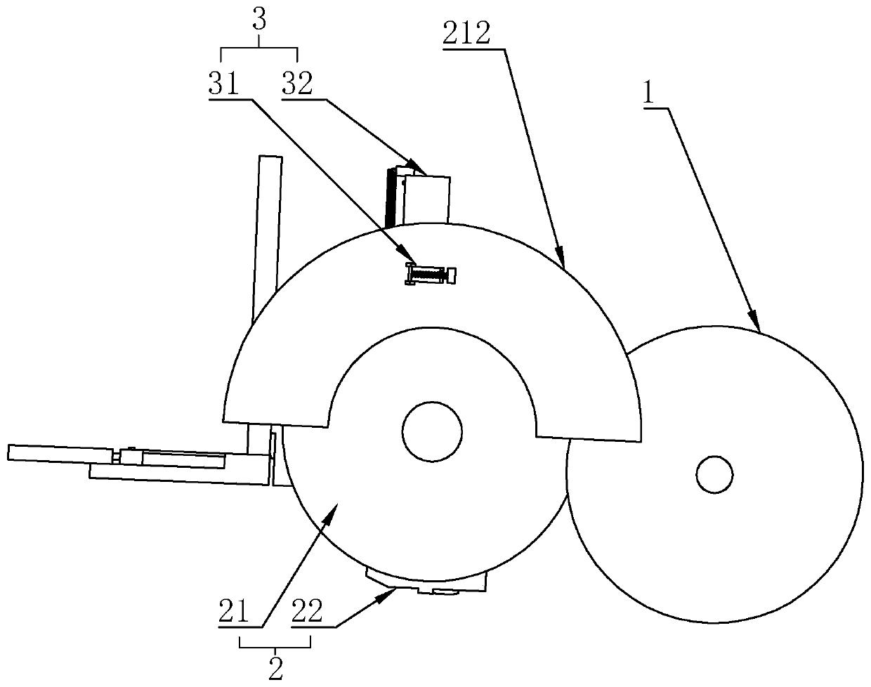
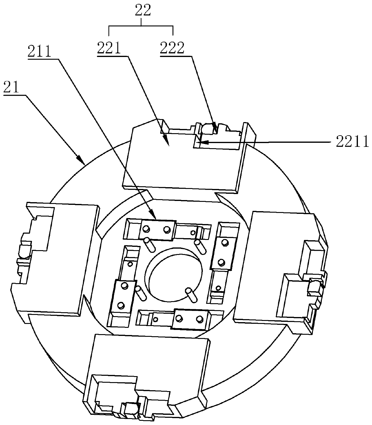
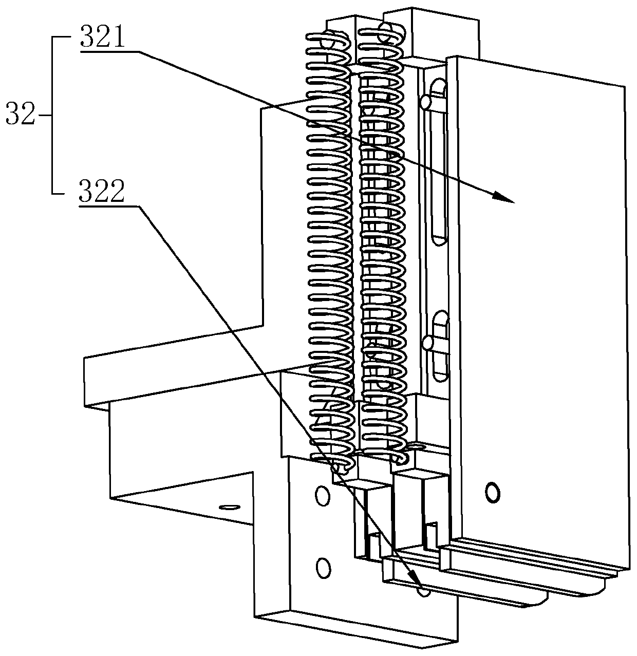
[0042] As an improved specific embodiment, the position adjustment mechanism 3 includes a left and right adjustment assembly 31 and an up and down adjustment assembly 32. When the clamp head 22 moves to the position adjustment mechanism 3, the clamp head 22 releases the clamped blade, and moves up and down. The adjustment assembly 32 adjusts the up and down position of the blade, and the left and right adjustment assembly 31 adjusts the left and right position of the blade. The up and down adjustment assembly 32 includes an adjustment base 321 and an adjustment pressing block 322, and the adjustment base 321 is fixed on the mounting plate 212. Above, the adjustment pressing block 322 is reversibly arranged on the lower side of the adjustment base 321, and is elastically connected to the adjustment base 321. When the chuck 22 moves to the bottom of the adjustment base 321 with the blade, the adjustment pressing block 322 presses The blade on the chuck 22 cooperates with the chuc...


PUM


Abstract

The invention discloses a manufacturing method for vanes of a vane pump. The manufacturing method comprises the following steps: step I, using a band sewing machine to cut out basic vane blank, and unloading the basic vane blank; step II, milling double side surfaces of the vane blank through a milling machine; step III, flatly grinding the vane blank milled by the milling machine; step IV, thermally treating the flatly grinded vane blank; step V, grinding the thickness and the height of the vane blank subjected to thermal treatment, and performing rough polishing on the vane blank; step VI, grinding one side, which is in contact with a pressurizing cavity, of the vane blank; step VII, grinding height and width of vane semi-finished products, and performing rough polishing on the vane semi-finished products; and step VIII, cleaning the sorted vane finished products. According to the manufacturing method for the vanes of the vane pump disclosed by the invention, the steps I to VIII areset, so that vanes can be effectively produced; and moreover, in the production process, multiple parts of the vanes are grinded by many times, so that smoothness of the vanes is effectively improved.

Description

technical field [0001] The invention relates to a manufacturing method, more specifically to a manufacturing method of vane pump blades. Background technique [0002] The vane pump is a kind of booster pump commonly used in the prior art. Through the action of the vane pump, a pressurization operation can be effectively realized for the existing liquid or gas, so as to achieve the effect of providing pressure. [0003] The pressurization principle of the vane pump is mainly to set a pressurized chamber, a rotating shaft can be rotatably set at the center of the pressurized chamber, and a plurality of vanes can be slidably arranged in the rotating shaft. During the working process, The centrifugal force generated by the rotation of the rotating shaft causes the blades to be thrown out, and then fit together with the wall of the pressurized chamber to ensure the effect of sealing and pressurizing, so the pressing sheet and the wall of the pressurized chamber will contact and r...

Claims


Application Information

Patent Timeline
IPC IPC(8): B23P15/02
CPCB23P15/02
Inventor 卢增亮
Owner 缙云县耐而特机械制造有限公司
Learn More