Foundation pit supporting device for civil engineering

A technology of foundation pit support and civil engineering, applied in the direction of infrastructure engineering, excavation, construction, etc., can solve the problems of low reuse efficiency and narrow application range of support devices, and achieve high reuse rate and wide application range Effect

Inactive Publication Date: 2019-09-13
HUANGHE JIAOTONG UNIV
View PDF8 Cites 6 Cited by
  • Summary
  • Abstract
  • Description
  • Claims
  • Application Information

AI Technical Summary

Problems solved by technology

[0003] At present, when supporting foundation pits, plates or anchors are generally used to support shallow foundation pits, and methods such as sprayed concrete on the surface of foundation pits or drilled piles are used to support deeper foundation pits. There are many types and

Method used


Image

  • Foundation pit supporting device for civil engineering
  • Foundation pit supporting device for civil engineering
  • Foundation pit supporting device for civil engineering

Examples


Embodiment 1

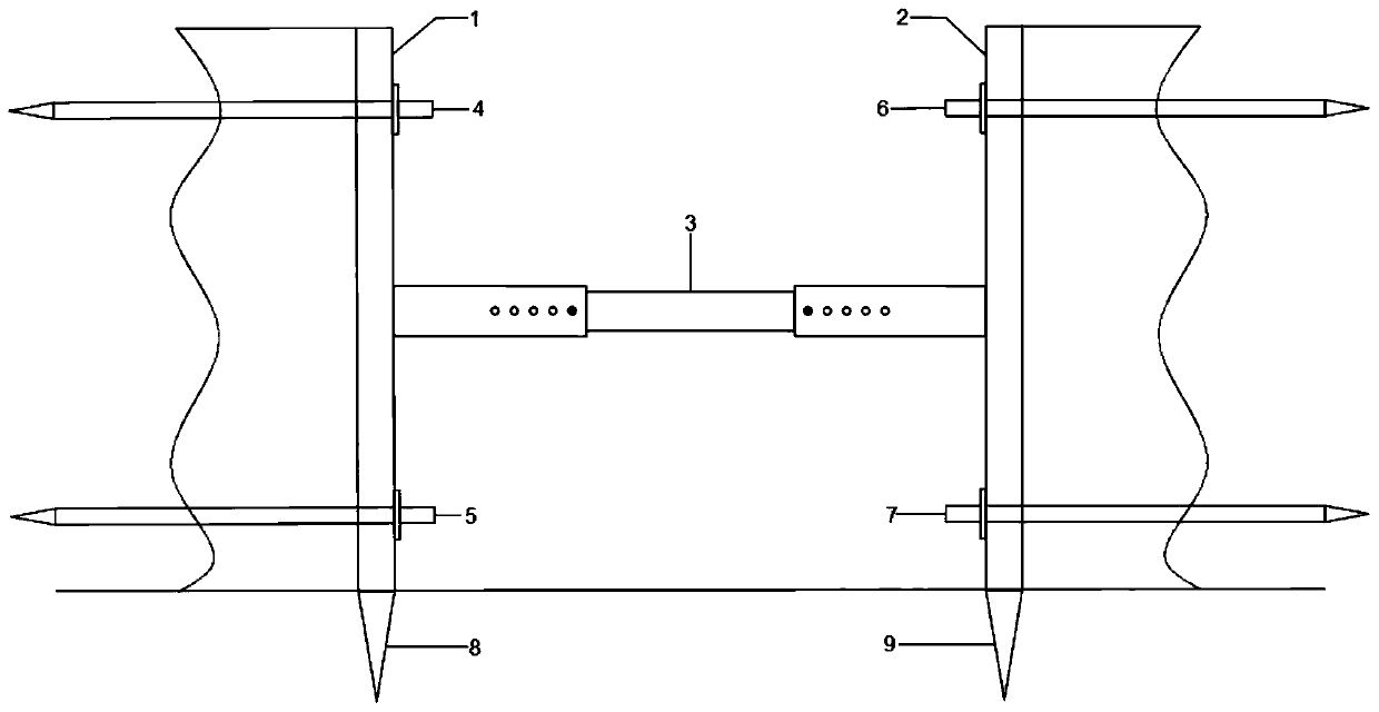
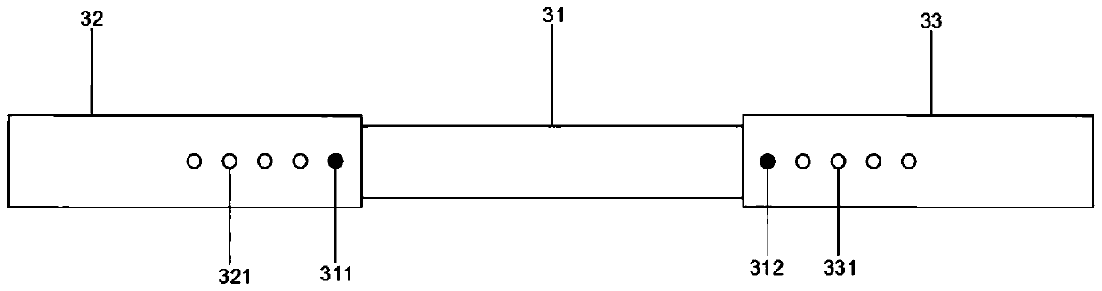
[0025] Embodiment 1: refer to Figure 1-2 , including a flat plate one 1 vertically close to the side wall of the foundation pit, a flat plate two 2 vertically close to the side wall of the foundation pit, and a telescopic rod 3 horizontally connecting the flat plate one 1 and the flat plate two 2, the flat plate one 1 Anchor rod one 4 and anchor rod two 5 are horizontally inserted in the upper and lower parts, respectively, for horizontal reinforcement of plate one, and anchor rod three 6 and anchor rod four 7 are horizontally inserted in the upper and lower parts of said plate two 2, respectively, for horizontal reinforcement. Reinforce the plate two, the bottom of the plate one 1 is provided with a sharp cone one 8, which is used to vertically reinforce the plate one, and the bottom of the plate two 2 is provided with a sharp cone two 9, which is used for vertically reinforcing the plate two.

[0026] The structure of the first plate 1 is the same as that of the second plat...

Embodiment 2

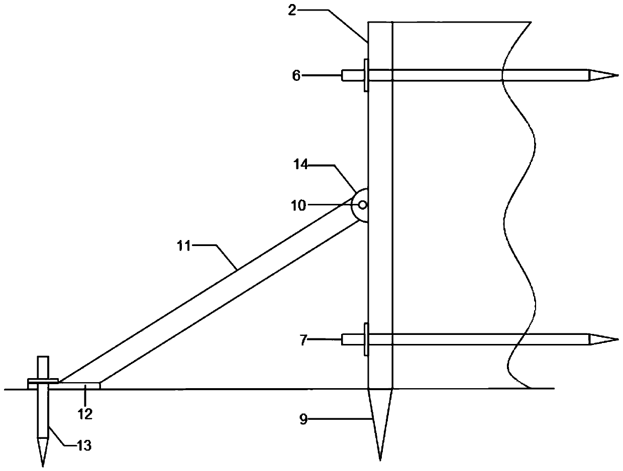
[0028] Embodiment 2: refer to image 3 , the difference from the above embodiment is that a base 14 is provided in the middle of the plate two 2, and the base 14 is hinged to the rotating rod 11 through the rotating shaft one 10 to adjust the inclination angle of the rotating rod 11. The end of the rod 11 is horizontally fixed to the support plate 12, and the side of the support plate 12 away from the rotating rod 11 is vertically inserted with an anchor rod 5 13 for vertically reinforcing the support plate 12 on the ground.

Embodiment 3

[0029] Embodiment 3: The upper part of the flat plate 1 is provided with a connecting column 17, the lower part of the flat plate 1 is provided with a groove 1 compatible with the connecting column 17, and one side of the flat plate 1 is provided with a connecting column 1. The second column 18, the other side of the first plate 1 is provided with a groove 2 matching the second connecting column 18. The sectional view of the first connecting column 17 and the sectional view of the second connecting column 18 are T-shaped or elliptical, and the sectional view of the groove one and the sectional view of the groove two are connected with the connection The sectional view of the first column 17 matches the sectional view of the second connecting column 18 . The upper part of the plate one 1 is provided with a lock one 19, and the lower part of the plate one 1 is provided with a lock two 20 matched with the lock one 19, which is used for locking a plurality of plates spliced ​​toge...


PUM


Abstract

The invention discloses a foundation pit supporting device for civil engineering,and relates to the technical field of civil engineering foundation pit support. The foundation pit supporting device for civil engineeringcomprises a first flat plate, a second flat plate, and a telescopic rod connected with the first flat plate and the second flat plate in a horizontal mode;a first anchor rod and a second anchor rod arehorizontally arranged on the upper part and the lower part of the first flat plate respectively in an inserted mode,a third anchor rod and a fourth anchor rod arehorizontallyarranged on the upper part and the lower part of the second flat plate respectively in an inserted mode, a first pointed cone is arranged below the first flat plate, and a second pointed cone is arranged below the second flat plate. According to the foundation pit supporting device for civil engineering,the support width of the entire supporting device can be adjusted according to the differences of thewidths of foundation pits, according to the differences of the depths of the foundation pits,the supporting manner can be changed, the supporting height of the entire supporting device is adjusted, meanwhile the supporting device can be spliced and repeatedly used, the application range is wide, the repetitive utilization rate is high, and the foundation pit supporting device for civil engineering is very suitable for use in civil engineering foundation pit support.

Description

technical field [0001] The invention relates to the technical field of civil engineering foundation pit support, in particular to a foundation pit support device for civil engineering. Background technique [0002] The foundation pit is an earth pit excavated at the foundation design position according to the base level and foundation plane size. Before excavation, the excavation plan should be determined according to the geological and hydrological data, combined with the conditions of the nearby buildings, and the waterproof and drainage work should be done well. If the excavation is not deep, the side slope can be used to stabilize the soil slope, and the slope size is determined according to the relevant construction engineering regulations. For those with deep excavation and nearby buildings, the foundation pit wall support method, shotcrete retaining wall method, and large foundation pit even adopt methods such as underground diaphragm wall and column-type bored pile ...

Claims


Application Information

Patent Timeline
IPC IPC(8): E02D17/04
CPCE02D17/04
Inventor 高卫亮陶亚萍马健华李娜
Owner HUANGHE JIAOTONG UNIV
Why Eureka
Try Eureka